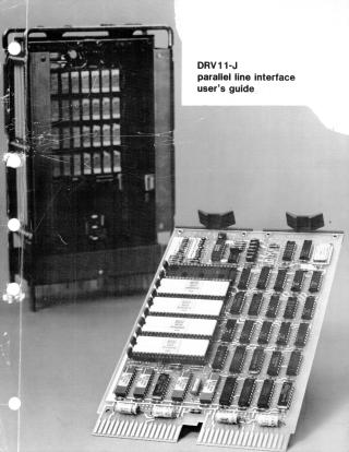
Digital PDFs
Documents
Guest
Register
Log In
EK-DRV1J-UG-002
2000
70 pages
Original
24MB
view
download
OCR Version
10MB
view
download
Document:
DRV11-J Parallel Line Interface User's Guide
Order Number:
EK-DRV1J-UG
Revision:
002
Pages:
70
Original Filename:
OCR Text
DRV11-J parallel line interface user’s guid DRV11-J parallel line interface user’s guide. - EK-DRV1J-UG-002 digital equipment corporation * marlboro, massachusetts ‘ 1st Edition, December, 1979 2nd Edition, Novcmbcr, 1980 Copyright © 1979, 1980 by Digital Equipment Corporation All Rights Reserved The material in this manual is for informational purposes and is subject to change without notice. Digital Equipment Corporation assumes no responsi- bility for any errors which may appear in this manual. Printed in U.S.A. This document was set on DIGITAL’s DECset-8000 computerized typesetting system. The following are trademarks of Digital Equipment Corporation, Maynard, Massachusetts: DIGITAL DEC PDP DECUS UNIBUS DECLAB DECGCsystem-10 DECSYSTEM-20 DIBOL EduSystem VAX VMS MASSBUS OMNIBUS OS/8 RSTS RSX IAS MINC-11 11/80-15 CONTENTS Page * * sk pd ik vk, e . Ld o ok - RV RV RV.RV.RV RV RV RV I ., * k. * k. * NENE SR CHAPTER 1 INTRODUCTION GENERAL DESCRIPTION .....ieeeeccccrerreee e cesserrae e e s e s e s ssneaese e e s s e aens FEATURES ...ttt ettt e e s et e e e s s satna e e s s s s aa e e e s s nsaaaeesanannnaas DOCUMENTATION.......coiiiiteeeecrreee et e s essrrre s e e s ssrte e e e s ere s e e e s s sseaneeesanns DIAGNOSTIC SOFTWARE ...ttt eee e e aaeeae eSPECIFICATIONS.................. eeeeeeresereeeeeersteeeeseanrbteeeeearrteeeeaarbrtaeeaaerrreaeeeeennrrans Physical SPeCifiCations...........cceiiiiiiiiiiiiiiiieiienciiiree e Electrical SpecifiCations.......ccccccveiiviiinnreeiiiiiciiireeeeeeeensernre e e s scnraaeeeeeens Environmental SpecifiCations ........ccccceveeeiiiiiiiiiimiiciinieeece e Operating and Storage Temperature Ranges ...........ccccceeeeviiniiceneennnnns Relative Humidity.......cccooeveveieiieiiiiieiecccceeeee e Airflow during Operation.........cccccoeieieiiiiiiieiiieciereeeeeeeceeirreeee eee ABEUAE ...ttt ee eeese e e e e e e e e rraeanees INSTALLATION ...ttt ecretee e e essrarre e enea e s s s ssanaa e e seanraaaeeseansnns 1-1 1-1 1-2 1-2 1-2 1-2 1-2 1-3 1-3 1-3 1-3 1-3 1-3 CHAPTER 2 FUNCTIONAL DESCRIPTION 2.1 GENERAL DESCRIPTION .....cccoiiiiiirieiiereeeeeeeneeen,rreeeeens eereea—reeeean———— 2-1 CONTROL/STATUS REGISTERS ..., 2-1 DATA BUFFER REGISTERS................. eeteeeerereeeeeeeeeiateeeeaeniabaeeeearatateaeeaerarnnaes 2-1 INTERRUPT CONTROL ...ttt cseeee e e esesevane e e aessnnaaaee e eena 2-1 Functional Description ........c.occevviiiiiiiiiiciiiiiiciiiieccciccecccee e 2-7 Interrupt Controller Interface...........cccooviiiiiiiiiiiiiieee e, 2-7 Interrupt Controller Operating Description............ccccoeeeeeiiiivrieeeeeeeeeccnrenee. 2-9 Interrupt Control RESet........ccummiiiiiiiiiiiieeeeecerre e 2-12 Interrupt Control Register Description..........ccccocevviieiiiciiiiiiecceiieeecee e, 2-13 StatuS REISter . cce i e e 2-13 Command Register ........................ e eeeeeeeererereeeereeeerrerateeeeeaaarernnrnrraaeeens 2-14 Mode RegiSter....ccciiiiiiiiiie e e e e e e e e e s e e e 2-14 Interrupt Request Register (IRR)..........ccevveeiiiininnnnie, veerrrrrerreenennennnees 2=14 Interrupt Service Register (ISR).......coooiiiiiiiiiiiiccceeee, 2-15 Interrupt Mask Register (IMR) ..., N 2-16 Auto-Clear Register (ACR)..... oo e 2-16 Vector Address MemOTY .....oooocciiiiiiiiiietieeeeeee e eeeecceenerae aeeeeeeeae e 2-16 OPERATING OPTIONS ....ttt eee e e e e e rnaaa e e e e s nnaaee e e enas 2-17 Interrupt Priority Mode Selection...........ccccoviviiiiiiiiiiiiiiiiiecccceeeieeeeeeeceeee 2-17 Individual Vector or Common Vector Mode...........ccceeeenriieeiieiiieciieeee, 2-19 Interrupt or Polled (Flag) Mode...........cccoeenrviimriieiecreee ee 2-19 Mode Register Bit 3 .......coooiiiiiiiiiiiiee, 2-19 TRQ Polarity Option........ccccoiiiiiiiiiiireiieiiccciiereee e ceeccierre e e e e eernnraeeeeeeeeeeans 2-19 Register Preselection Option.........cccviiiiiiiiiiiiiiiiiiecccccce e 2-19 Master Mask OPtion ......ccooeiiiiiiiiiiiiiiiiiceeceereeeereeee e ee e eee e eeee e eeeee e 2-20 SYSTEM OPERATING SEQUENCE ... e eevree e 2-20 COMMAND DESCRIPTIONS ................. Ceeeteeeessesasnnisteesasessasaransassrssesssrsnsnnaranne 2-21 RESEL ... ittt e e e e e et e et e r e e e e e e e e e aaaeeeeeeaeanraranneaaanes Clear IRR and IMR ...t aas Clear Single IMR and IRR Bit........cooooiriimiiiiciieeeeeeeccreee e, Clear IMR ...t e e ee e e e e e eer e e e s e nnnraeeeeas i1l 2-21 2-21 2-21 2-21 CONTENTS (Cont) Page 2.7.5 2.7.6 2.7.7 2.7.8 2.7.9 2.7.10 2.7.11 2.7.12 2.7.13 2.7.14 2.7.15 2.7.16 2.7.17 2.7.18 2.7.19 2.7.20 Clear Single IMR Bit ......cc.ocoiiiiii e iieiceiec e, cee SELIMR ...tett et eer e e et Set Single IMR Bil......covioiiiiiieeccicccee et ee e e e e, cecteee CIEAr IRR ...tett e e e r e e, Clear Single IRR Bit........cccoooveviieniiciicieeeereeeeeenn, ett e e tanrrareeaeeas t SEtIRR .tt e et e e et Set Single IRR Bit ......oceiiioieeieecccce et Clear Highest Priority ISR Bit ......c.cocooviiieiiienieeieeeeee e CIEAT ISR ...t et s ett e et e eae e e e s s e s s eseseseeomeeas Clear Single ISR Bit ....c..ooiiiiiiieiieie et iceeeetee e e ee e e Load Mode Bits MO through M4 .............oooiiieiiieeeeeeeeeeeeeeeeeeee e, Control Mode Bits MS, M6 and M7 ..........ccooovueomiemeeeeeeeeeeeeeeeeeeeeeeeens Preselect IMR for WIItIng ......coouviiiiiiiiiiiicceec e Preselect ACR fOr WIiting......oveccveeeieieiieiiceceecee e ceeeeeee Preselect Vector Address Memory for Writing ...................... cerrreeeeeeeee———— Coding B2, B1, BO Field Commands ..........uovveeeeeeeeeeeeeeeeeeeeeeeeeeeeeeeeeeee CONFIGURATION GENERAL DESCRIPTION ......oootiiiieieeeicr et eee e tesetesere e eceeee e e FACTORY CONFIGURATION ......ooooiiiiiiticeeeeeeeeeceeeereeseseeereessseesse senes DEVICE ADDRESSES ...t eteeertee e eeeeeseeeseeseeeeees tt s esne e, DEVICE ADDRESS JUMPERS. .........ooiiieeeeeeeeeeeeeeeeeee eeeeeeee INTERRUPT VECTOR ADDRESSES..........ooootootieeeeeeeeeeeeeeeeeeeeeeees e, CHAPTER 4 INTERFACING 4.1 4.2 4.3 4.9 INTERFACE CONNECTORS ........o oottt ee e ee e e e e INPUT/OUTPUT SIGNAL FUNCTIONS. ................... reeeereeeeeeeeerere—————eeeeenran INPUT/OUTPUT SIGNAL ASSERTION LEVELS ....................................... INPUT/OUTPUT SIGNAL LOOPBACK CONNECTIONS ......oooeeveeeenn INTERFACE CABLE ..ot e evee e s e tt es et INPUT/OUTPUT FUNCTION TIMING .......coeoouirireeeeeeereeeeeereeereeesreseeessens INPUT DATA OPERATION ...ttt ee et eeeereeeesee e e esessees e OUTPUT DATA OPERATION .......oooiiiieeieeeeeeeeeeeeeeeeeeeeeeeeeseeees ess e, INTERRUPT OPERATION ...ttt ee e eee s e e e e e s e CHAPTER 5 PROGRAMMING EXAMPLES N SN UV W W W W W CHAPTER 3 4.4 4.5 4.6 g W DN e 4.7 GENERAL DESCRIPTION .....oooiiiiieeeeieeeeeteeeeeereeeeeeeeneeeeneeensne s e PROGRAMMED DATA TRANSFER WITHOUT HANDSHAKING......... PROGRAMMED DATA TRANSFER WITH HANDSHAKING ................... INTERRUPT-DRIVEN TRANSFER .......coooviiiiiieeeeee e e e e e ee e CHAPTER 6 OPTIC ISOLATOR INTERFACE EXAMPLE v 2-22 2-22 2-22 2-22 2-22 2-22 2-23 2-23 2-23 2-23 2-23 2-23 2-24 2-24 2-24 2-25 3-1 3-1 3-1 3-5 3-5 4-1 4-1 4-1 4-5 4-5 4-5 4-9 4-9 4-9 5-1 5-1 5-1 5-3 FIGURES Figure No. 2-1 2-2 2-3 2-4 2-5 2-6 2-7 2-8 2-9 2-10 2-11 2-12 2-13 3-1 3-2 4-1 4-2 4-3 4-4 4-5 4-6 5-1 5-2 5-3 5-4 6-1 Title DRV11-J Block DIagram.........ccccceirviiirieieecieenceeeecneccireenneceseeseseesssseeseeees veees CSRA Bit Assignments..................... ceeveeanannas et etteeettter ettt taaattrattatateanratarararaaaraas CSRB Bit Assngnments ....... Ceeereeeeeeerenraaananens vvaes CSRC Bit ASSIBNIMENLS .....cocueruriereeieiieniecereeeristeceseeseresesstesseesseesssessessseessssssaesses CSRD Bit ASSignments..........ccccccuvveerineeeieieeeeereecneeennn. ceeveeenerenn vrerreeens veevevnnns eee Data Buffer Register Bit ASSINMENtS ........ccceevvvuiiiiriieiiiieeeeeeeereereeesseeens vevvreeeenes Group 1 and Group 2 Interrupt Controller Interconnections.........cccceeeeeeeeeeeeeneecinnne. veevnnrenana, OO UPPPUUPUURURRD. Intergroup Priority Resolution Timing.................... eerereernaranavvnraeees veeereeeaneneene Interrupt Controller Block Diagram...........ccccccceevvveevveenneennnen. ceeeenerraens erereneeraaes CSRA and CSRC Status Registers’ Bit Assignments........ ceeeeeeeeenrnnes vreeeerreneennnes Mode Register Bit ASSignments ...........ccoceeevveveeeevveeeeeneererenennn. eerereereeenas vrveeereeees DRV11-J Vector Address Format ...................... Ceeereeeesernrrtaeee e ennnaaeanaeane eae vereeeeens Rotating Priority Mode .........ccoovvevreevmriiirieiieeeeeeieeeeene ceereerreeererenees crerennns . DRYV11-J Jumper Locations.........cccccueeervvivinnnreencnnnenn. crereees Ceereeeessseessrsrnresnnrerenes DRYV11-J Device Address Format................. OO O SRS PUPUPPUUPRRRTRC DRV11-J I/O Connector Pin Locations........................ ceeeeeeraens ceereens reeeeeeeneenaaes I/O Bus Interface, Simplified Schematic.......ccccccveevvvvennnnn. ferereeresenreeeerneronnarane DRYV11-J I/O Function Timing ...........cccccveuvenneen..... e eanes cerveens ceeereaneeans Input Data Transfer Sequence ...........cccccuvevvueevvnricvreecceecnnnn. ceeeeenraeees veerereeereee Output Data Transfer Sequence ..........cccoecvvevvvecviecieciieeeee e, ceeerrans vereenene Interrupt Sequence...........cceeevveenneen. feeeeenrreeeeeareeeeeaaaeeeannaeaans cererenraeranns ceeeenns . Example of a Programmed Data Transfer without HandshaKing ............cooovuiiiiiiiiiiiniiiiieeccecece e eeeeae e e vevenees Example of a Programmed Data Transfer with Handshaking................... ceeesereantreannreanna—————— vvveeens vevrrennrennnn, vererrrrererennaaes Example of an Interrupt-Driven Output ngram ............... Ceeereeererernrrearaeeeeerenannns Example of an Interrupt-Driven Input Program.................... ceveerereeaseeerereeseeennns e Example of an Optic Isolator Interface................... ceereeeenes vevvveens crerreeereeeereeaeaae e Page 272 2-3 2-4 2-5 276 22T 2 . 2-10 2-11 2-14 2-15 2=17 2-18 3=2 . | 4-2 4-4 4-7 4-10 411 4-12 5-2 5-3 5-4 -5 6-2 TABLES Table No. 1-1 2-1 2-2 2-3 2-4 2-5 2-6 2-7 2-8 2-9 Title DRV11-J Module Pin Assignment .............coeovevevven.... Ceeteeeetteettrtteaar—a—————————————————— CSRA Bit Functions and DescCriptions...........c..ooueveeeveemereeeseooeeeeeeoon.e CSRB Bit Functions and DeSCIiptions ..........co.oooveveeeereee oo CSRC Bit Functions and DesCriptions............ceeeueeveverevvereerseseooseeoeoeeoeoeoon, CSRD Bit Functions and Descriptions..................e s e e e e e e e e e e e e e e e e e e e eeeeeeeees . Summary of Data Bus Transfers.............oo.covveonmeeneeeeeeeeeeeeeeeeeeeeeeeeeoeeeeos Interrupt Control Register and Memory Summary .............o.oeveveeeveevennn.. veeeenas Fixed Priority Mode ............ cesesereersnstninssrasstsansssssstostresaaassessareriesessseerietssetsioeerennenns Vector Address Memory Field Coding...........cccovvvveuveeennn..e a e e e e e e e e e neereneee Command Register B2, B1, BO Field Coding...........cocoovevoveeeeeeeeeoeoeeoeoo Page 1-4 2-3 2-4 2-5 2-6 2-12 2-13 2-17 2-25 2-25 TABLES (Cont) Table No. 2-10 3-1 3-2 3-3 4-1 4-2 4-3 4-4 Title | Page DRV11-J Command Code Summary.............. eeeeeeeenerennans Ceeeeeeeeeenrarareetaeeaeanennan 2-26 DRYV11-J Factory Jumper Configuration............e ereeeerreerrettaeeeeeaaanannnraees 3-3 DRV11-J Jumper FUNCLIONS .......cuuuiiiiiiiiiicciiiceiirieeeeeceennreeeeeecneeeeeeeeeeeeeeeeeeeceeeseeeees 3-4 DRVI11-J ReGiSters......cccovvueriireiiiieceriicnirinerneeeeneeennnsettereeaeeeeaerrraaateeeetaaaearnnnns 3-4 I/O Connector Pin Assignments ..................... eererebeee e te et e e enteeaae e s aae s aaeesaans 4-2 I/O Signal Functions............. SRR UU O PRTRUUPORUUPRTUPPTRROON 4-5 DRV11-J Loopback Signal Connections................. e ereerteeeeerteeeeeabaeeeeraaaeeaenarans 4-6 I/O Function Timing ToOlerance........ccccccovvuiiiriieeiiierrieeeeeeeeeee e 4-8 Vi CHAPTER 1 INTRODUCTION 1.1 GENERAL DESCRIPTION The DRV11-J is a double-height parallel line interface module designed for use in LSI-11 microcomputer systems. It contains four programmable ports designated A, B, C and D. Each port contains 16 I/0 lines and is capable of transferring a 16-bit word between the LSI-11 bus and the user device(s). Data word transfers in or out of the DRV11-J are accomplished by the assertion of two control signals at each port of the DRV11-J and two control signals asserted by the user device to its respective port. These control signals must be asserted in a protocol sequence while observing timing constraints to ensure an orderly data transfer. The protocol sequence is described in Chapter 2. The DRV11-J will also accept interrupt requests from up to 16 1/0O lines to generate up to 16 individual vector addresses. This interrupt capability for real-time response makes it useful for sensor 1/0 applications. The DRV11-J may also be used as a general-purpose interface to custom devices, or two DRV11-Js may be connected together as a link between two LSI-11 buses. The DRV11-J contains two programmable mode registers that provide a number of operating modes to customize the module configuration for different system applications. The module may be programmed for use in vectored-interrupt-driven systems or software-polled systems. When used in vectored interrupt systems, the module may be programmed to operate in either a fixed priority or a rotating priority resolution mode. In addition, the module may be programmed to generate either a common vector address or individual vector addresses in response to user device(s) interrupt requests. Additional operating options available under program control include the selection of an active high or active low interrupt request polarity, preselection of internal registers, and the selection of a master mask bit to arm or disarm the interrupt capability of the DRV11-J. All of the operating modes and options are described in detail in Chapter 2. The DRVI11-J also contains two RAMs that are used to store programmed interrupt vector addresses. One 8-bit RAM location is used to store each interrupt vector address. One vector address may be programmed for each of the 16 interrupt request inputs. ¢ & & ¢ o o 1.2 FEATURES The DRVI11-J contains the following features. Four 3-state 16-bit parallel I/O ports User-assigned device addresses Acceptance of up to 16 external interrupt requests Programmable interrupt vector addresses Program-controlled input/output operations Programmable operating modes: Interrupt Controller Mode — Interrupt-driven Priority Modes - Fixed or Rotating Vector Address Selection - Individual or common vector 1-1 1.3 DOCUMENTATION In addition to this user’s guide, refer to the Field Maintenance Print Set, MP00866, for information on the DRVI11-J module. 1.4 DIAGNOSTIC SOFTWARE Diagnostic software is available for troubleshooting, fault isolation, and verification at both the module level and system level. Two diagnostics are required for testing at the module level and these must be run in sequence. A DECX 11 module diagnosticis required to test the module at the system level. Turnaround cable BCO5SW-02 must be installed with a half twist to J1 and J2 when running the module- and system-level diagnostics. The diagnostic softwareis designated as follows. e e 1.5 CVDRCAO Part 1 CVDRDAOQO Part 2 | DECXI11 Module CXDRJAO SPECIFICATIONS | | | | | The following defines the physical, electrical and environmental specifications for the DRV11-J module. 1.5.1 Physical Specifications Identification Size MB049 Double-height 22.8cm X 13.2cm (8.91in X 5.21n) 1.5.2 Electrical Specifications Power +5Vdc £ 5% @ 1.8 A (maximum), 1.6 A (typical) Bus Loads ac 2 dc 1 1/0 Si'gna‘l Electrical Parameters: Data Buffer 3-State Outputs Data Buffer Inputs V(OL)=0.5V@I(OL) = § mA I(IL) = -0.2mA @ V(IL) = 0.4V V(OL)=0.4V@I(OL) =4 mA V(OH) =24V @ I(OH) = -2.6 mA Protocol Signal 3-State Outputs V(IH)=20uA @ V(IH) = 2.7V . Protocol Signal Inputs V(OL)=0.55V @ I(OL) = 64 mA V(OH) =24V @ I(OH) = -15mA Termination = 120 - I(IL)=-27TmA @ V(IL)=0.5V I(IH) =80uA @ V(IH)=2.7V 1-2 Environmental Specifications 1.5.3 The DRV11-J module may be operated or stored in the following environmental conditions. 1.5.3.1 Operating and Storage Temperature Ranges Operating range: 5° to 60° C (41° to 140° F) Storage range: -40° to 66° C (-40° to 150° F) If the module is not within its operating temperature range, move it to an area within the range and allow it to stabilize for a minimum of five minutes before operating. Also, derate the maximum operating temperature by 1° C (1.8 ° F) for each 305 m (1000 ft) of altitude above 2440 m (8000 ft). 1.5.3.2 Relative Humidity Storage: 10% to 90%, noncondensing Operating: 10% to 90%, noncohdensing 1.5.3.3 Airflow during Operiation - Provide adequate airflow to limit the inlet-to-outlet temperature rise across the module to 5° C (9° F) when the inlet temperature is 60° C (140° F). For operation below 55° C (131° F), limit that rise to 10° C (18° F) maximum. 1.5.3.4 Altitude | Storage: Operating: The module will not be mechanically or electrically damaged at altitudes up to 15,240 m (50,000 ft), 90 mm mercury. Up to 15,240 m (50,000 ft), 90 mm mercury. Note: Derate the maximum operating temperature by 1° C (1.8° F) for each 305 m (1000 ft) of altitude above 2440 m (8000 ft). 1.6 INSTALLATION The DRV11-J is a bus request level 4 module and must be installed in an LSI-11 backplane dual-option slot following the rules for position-dependent interrupt priority configurations. In position-dependent configurations, peripheral devices with the highest priority must be installed closest to the processor and the remaining devices placed in the backplane in decreasing order of priority, with the lowest priority module farthest from the processor. Before installing the module(s) in the backplane, check that the proper device address jumpers are installed. Three standard LSI-11 bus addresses are reserved for the DRV11-Js. If the application requires more than three DRV11-Js, the additional modules must be assigned addresses located in the user-reserved address space. Chapter 3 describes the address configuration procedure. The standard factory jumper configuration is described in Table 3-1, and Figure 3-2 shows the device address format. CAUTION DC power must not be applied to the backplane when installing or removing modules. The DRV11-J’s functionality must be proved after installation by performing an acceptance test. The acceptance test consists first of running the basic system diagnostics and then running the DRV11-J module-level diagnostics listed in Paragraph 1.4. 1-3 Module Pin Assignments The DRV11-J module pin assignments are described in Table 1-1. Table 1-1 DRV11-J Module Pin Assignment Connector A Side 1 Signal Pin Connector B Side 2 Side 1 Signal Signal Pin Side 2 Signal BIRQ 5L A +5V NC A +5V BIRQ6L B NC NC B NC NC C GND NC NC C GND D NC NC D NC NC F BRPLY L NC F BDAL3L NC H BDIN L NC NC H J BDAL4L BSYNCL NC NC J BDALSL K BWTBT L NC K NC BDALG6L L BIRQ 4 NC L BDAL7L NC M BIAKIL NC NC M "BDALSL N BIAKOL NC N BDALY9L NC P BBS7L BIRQ7L NC P BDAL I0OL R BDMGIL NC NC R S BDALIIL BDMGOL NC GND S T BINITL BDAL I2L GND NC T U BDAL I3 L BDALOL NC NC \% U BDALIL BDAL 14 L NC A% BDAL I5SL NOTE: . Connector A, pin A, side 1 corresponds to bus pin AAI. 2. NC = no connection. ' o, | CHAPTER 2 FUNCTIONAL DESCRIPTION 2.1 GENERAL DESCRIPTION The DRV11-J contains the logic necessary to provide communication between the LSI-11 bus and up to four user devices in 16-bit word lengths via four 1/O ports. Four control lines associated with each of the four ports ensure orderly information transfers. Word transfers are executed by programmed 1/0O operations or interrupt-driven routines. Write data is output by the DRVI11-J to the I /O bus through 3-state data latches, and read data is input through unlatched bus buffers. Figure 2-1 shows the main logic functions performed by the DRV11-J module. All control/status and 1/O data transfers take place over a bidirectional internal bus (TSD <15:00>) on the DRV11-J. The module contains four I/O buses, one for each port (A, B, C and D). Each port has an associated control/status register (CSRA, CSRB, CSRC or CSRD) that contains status information when read and command words when written. All ports have 16 bidirectional 3-state lines and perform controlled input/output operations. Note that port A is the only port that will perform bit interrupt functions in addition to input/output data transfers. The 16 external interrupt requests are functionally divided into two groups of eight lines, referred to as group 1 and group 2. 2.2 | CONTROL/STATUS REGISTERS The control/status registers (CSRA, CSRB, CSRC and CSRD) are read/write byte-addressable registers with bit assignments as shown in Figures 2-2, 2-3, 2-4 and 2-5. The function and description of the control/status register bits are described in Tables 2-1, 2-2, 2-3 and 2-4. 2.3 DATA BUFFER REGISTERS The four data buffer registers (DBRA, DBRB, DBRC and DBRD) are 16-bit word-addressable registers. They are used as latched output data buffers when the DRV 11-]J is in output mode (write) and as unlatched bus buffers in input mode (read). The contents of the output data buffers may be examined while the DRV 11-J is in an output mode by performing a read operation of the input data buffers. This ability to examine the output data buffers in the output mode provides software access to the internal conditions of the DRVI11-J. The latched output data buffer registers DRBA through DBRD are not cleared by BINIT. The bitassignment is the same for all registers and is shown in Figure 2-6. 2.4 INTERRUPT CONTROL The DRV11-J is capable of monitoring 16 lines to generate 16 vectored interrupts. The interrupt control is performed by a DCO003 interrupt logic chip and interrupt controller chips. A functional description of the signals required to initiate interrupts and the DRV11-J registers used for programming, reading and writing the internal registers of the interrupt controllers is given in Paragraph 2.4.1. An operating description of the interrupt controllers is given in Paragraph 2.4.2, and the internal registers of the interrupt controllers are described in Paragraph 2.5 2-1 HOLI3A ‘'VYSD 84SD diy 13 2-2 auso ML AHG AQH Q ¥ <0:G10/1 ¥- 33514T80MH0L7NOD03 < , ¥34ngayv v48Q . . — ” DLLNdNOHD4IL3I7N1I04DIY9ol o4l »w (N\dzZ3v4HaV)|AN1LIl.nO1do3E8yaS18sNmv—78[1d+g-1OoO2/N3iV7T1O3H8yLINODS<@e*«—r—o1.f|L1aVLoI'IN=M0iN'ovX8HH'sSv0Oa3y8 <L|e>Tvaq T1H4O93OH31LL15IY31N59O3D4 H1I4Q(NS0O{1B83GAH5}Le=f—11400H4INOD40S9‘90»|:iFHFsAL3LaCNSqAGANuTYMrGAGLEiQA‘AH1Edad2gYHHaQD8--~er R&e@_-((Z(Z(ZdLZuvVANvV)<YY)))0L:U57M11>V091L7HWL0isv01SIa8M3vHaNDg85VI8iIg7*egT7—y1—-A(VCO4LYS"0HYS3A350CNW4I0a.V_AA5HnIOV-L3ED0H|A*6]-LN.m—I5fDls3.ASdg3TNHvIOUQaYSO(y)v8FEALR)eTITyl.DHI%mA”&5-£o<0:DeYH>I<<00:'45>1>0S1ZitSEv8iILiayvVesLou¥Ol3tldLLLLLJIIIIouelJnNaNWNMmgXuyXXaXWm:yQDa8vg8;«—)I.vV1:4.,l)oPavHoyYH_V__y=8sS0OYAaaD/vl_,<SL0I:>IL<>S8_‘1LHYa5OO<ddS10))IH|:9O6S§1d0((H|F>)/O8H0L3-HV34/Ss819ANS(Q0nHNYAGHAQE-A1HdAQYvHH3a¥":z!r Z"A@(rzvs)v)709ONWAaS8PE601S—1Nst3t4ya-3yv1—‘‘MLJOdHu<TNS0mOD:°30Y16LaD1Ay>Q8s80dS"1SyoHIA|Z<i:e>astK1y.odanyH34Nn8;<Z,A:£>1JvaTo81LHu,S82dvvHS8)<0':S51tFHF>L¥L3H0IS/3AAs1NSHNnNAGGQAAAHl4QTdyY8HdO8vH"~VK"e 13 )— 3NLdNY q0HINODe /OHIol LIEPHW 15 14 09 13 RDY UNUSED A ] 08 07 DIR| 04 03 02 c/s | Cc/S| C/s|cC/is| C/s C/S | C/S | C/S | 7 5 3 2 A ] 06 6 05 4 01 1 00 0 MR-4310 Figure 2-2 Table 2-1 CSRA Bit Assignments CSRA Bit Functions and Descriptions Bit Name Function Description 07:00 C/S7-C/SO0 Read/Write These bits are used in conjunction with CSRB bits<07:00> to program interrupt control group 1. They contain status information when read and command words when written. Unaffected by BINIT. (See Paragraphs 2.4.5.1 and 2.4.5.2 for status and command definitions.) 08 DIR A Read/Write DIRECTION A. Used for controlling DBRA. This bit, in conjunction with the USER RDY signal, controls the direction of data transfer. When the DIR bit is cleared, the DRV11J RDY output signal is asserted and the DRVI11-] is the input device. When this bit is set and the USER RDY signal is asserted, the DRV 11-J is the output device. The negation of either DIR or USER RDY causes the DRV11-J outputs to remain in their highimpedance state. Cleared by BINIT. IE Read/Write INTERRUPT ENABLE. Enables the DRV11-J to generate processor in- terrupts when set. Used to enable both group | and group 2 interrupts. Cleared by BINIT. Unused. Read as 0s. 14:10 15 | RDY A Read Only USER READY A. Used for controlling DBRA. When read, this bit yields the state of the USER RDY signal. A 0 means negated- and a 1 means asserted. This bit is used in conjunction with the DIR bit to enable DRV11J output operations. The user device asserts this signal when it desires the DRVI11-J to output data. Unaffected by BINIT. 2-3 15 [) RDY 14 13 1 12 10 UNUSED ] 09 08 > DIR 07 D7 | 06 05 04 03 02 01 00 D6 D5 D4 D3 D2 D1 DO ] MR-4312 Figure 2-3 Table 2-2 CSRB Bit Assignments CSRB Bit Functions and Descriptions Bit Name Function Description 07:00 D7-DO0 Read/Write These bits are used in conjunction with CSRA bits <07:00> to program interrupt control group 1. They contain information selected by the command word loaded through CSRA. The registers available are the IRR, ISR, ACR, IMR and the vector address memory. Unaffected by BINIT. (See Paragraphs 2.4.5.4 through 2.4.5.8 for a detailed description of the registers and their functions.) 08 DIR B Read /Write DIRECTION B. Used for controlling DBRB. This bit, in conjunction with the USER RDY signal, controls the direction of data transfer. When the DIR bit is cleared, the DRV11J RDY output signal is asserted and the DRVI11-J is the input device. When this bit is set and the USER RDY signal is asserted, the DRV11-J is the output device. The negation of either DIR or USER RDY causes the DRV11-J outputs to remain in their high- impedance state. Cleared by BINIT. 14:09 15 Unused. Read as 0s. RDY B Read Only USER READY B. Used for controlling DBRB. When read, this bit yields the state of the USER RDY signal. A 0 means negated and a 1 means asserted. This bit is used in conjunction with the DIR bit to enable DRV11- J output operations. The user device asserts this signal when it desires the DRVI11-J to output data. Unaffected by BINIT. 15 RDY C 09 10 11 12 13 14 U NUSED i 1 07 06 05 C/S C/S C/S C/S 03 02 01 00 C/S C/S C/ C/S 1 C ] | | 08 DIR 0 MR-4313 Figure 2-4 Table 2-3 CSRC Bit Assignments CSRC Bit Functions and Descriptions Bit Name Function Description 07:00 C/S7-C/S0 Read/Write These bits are used in conjunction with CSRD bits <07:00> to program 08 DIR C Read/Write interrupt control group 2. They contain status information when read and command words when written. Unaffected by BINIT. (See Paragraphs 2.4.5.1 and 2.4.5.2 for status and command definitions.) DIRECTION C. Used for controlling DBRC. This bit, in conjunction with the USER RDY signal, controls the direction of data transfer. When the DIR bit is cleared, the DRV11J RDY output signal is asserted and the DRVI11-J is the input device. When this bit is set and the USER RDY signal is asserted, the DRV11-J is the output device.The negation of either DIR or USER RDY causes the DRV11-J outputs to remain in their highimpedance state. Cleared by BINIT. Unused. Read as Os. 14:09 15 RDY C Read Only USER READY C. Used for controlling DBRC. When read, this bit yields the state of the USER RDY signal. A 0 means negated and a | means asserted. This bit is used in conjunction with the DIR bit to enable DRV11J output operations. The user device asserts this signal when it desires the DRVI11-J to output data. Unaffected by BINIT. 2-5 12 11 10 09 08 > UNUSED ] 07 06 p7 | o6 | 05 | 04 03 02 01 00 o5 | b4 | p3 | b2 | b1 | DO MR-4314 Figure 2-5 Table 2-4 CSRD Bit Assignments CSRD Bit Functions and Descriptions Bit Name Function Description 07:00 D7-D0 Read/Write These bits are used in conjunction with CSRC bits <07:00> to program inter rupt control group 2. They contain information selected by the com- mand word loaded through CSRC. The registers available are the IRR, ISR, ACR, IMR and the vector address memory. (See Paragraphs 2.4.5.4 through 2.4.5.8 for a detailed description of the registers and their func- tions.) 08 DIR D Read /Write DIRECTION D. Used for controlling DBRD. This bit, in conjunction | with the USER RDY signal, controls the direction of data transfer. When the DIR bit is cleared, the DRV 11J RDY output signal is asserted and the DRV11-] is the input device. When this bit is set and the USER RDY signal is asserted, the DRV 11-J is the output device. The negation of either DIR or USER RDY causes the DRV 11-J outputs to remain in their high- impedance state. Cleared by BINIT. 14:09 Unused. Read as 0s. RDYVD Read Only USER READY D. Used for controlling DBRD. When read, this bit yields the state of the USER RDY signal. A 0 means negated and a | means asserted. This bit is used in conjunction with the DIR bit to enable DRV11J output operations. The user device asserts this signal when it desires the DRV11-J to output data. Unaffected by BINIT. 2-6 I 15 14 13 - 11 10 09 08 1/0 BUS <15:8> i e 12 | | ] ] HIGH BYTE READ < 07 06 05 >le | | 04 03 02 01 00 1/0 BUS <7:0> J > | | | > | LOWBYTE READ | I > WORD READ/WRITE MR-4315 Figure 2-6 2.4.1 Data Buffer Register Bit Assignments Functional Description The interrupt control logic shown in Figure 2-1 consists primarily of a DC003 interrupt logic chip and two interrupt controller chips. Five LSI-11 bus control signals (BIRQ 4 L, BIAKI L, BIAKO L, BDIN L and BINIT L) are used by the interrupt control logic for initialization, sending interrupt requests to the processor, receiving the interrupt acknowledge signal from the processor, and sending the vector address to the processor. Each interrupt controller chip is responsible for monitoring a group of eight interrupt request inputs. Each group of eight interrupt requests is applied via IRQ buffers to an 8-bit interrupt request register (IRR) in the interrupt controller. The two interrupt controllers (group 1 and group 2) are programmed independently. The group 1 interrupt controller is programmed through the low bytes of CSRA and CSRB while the group 2 interrupt controller is programmed through the low bytes of CSRC and CSRD. The only commonalities of the two groups are priority resolution and the interrupt enable (IE) CSRA bit 9. Both interrupt controllers must operate in the same mode, either interrupt or polled. Each interrupt controller contains an 8-bit interrupt mask register (IMR) that may be used to disable the processing of any undesired interrupt requests. The group 1 interrupt controller has the higher priority and its enable output is connected to the enable input of group 2. Group 1 must be armed to accept interrupts with the master mask bit set in the mode register. When group 1 is armed, its enable output goes high, thus enabling group 2 interrupts. Therefore, whenever the interrupt mode is selected, group 1 must be armed, even if none of the group 1 interrupt requests are being used in order to pass the enable signal along to group 2. Group 1| and group 2 may be programmed to respond to either an active high or an active low transition on the interrupt request lines. A bit in the interrupt request register (IRR) is set whenever the corresponding interrupt request line makes an inactive-to-active transition and meets the active pulse width requirements. Active pulse widths 270 ns or greater will set the corresponding IRR bit, while pulse widths 30 ns or less are ignored. Active pulse widths between 30 ns and 270 ns may or may not set the IRR bit. 2.4.2 Interrupt Controller Interface The interconnections between the group 1 and group 2 interrupt controllers, their relation to the DRV1I1-J A I/0O bus and the LSI-11 bus are shown in Figure 2-7. Latched data address line LDAL 3 L or H, along with the SEL 0 L signal, is used to select group 1 for subsequent reading/writing through the low byte of CSRA or CSRB, or group 2 for reading/writing through CSRC or CSRD. Intergroup priority management is controlled by the enable-in (EI), enable-out (EO) and the response-in-progress (RIP) signals. Note that the IAK L, GINT, RIP, and PAUSE lines are respectively tied together. Group 1 is always enabled because its enable-in (EI) pin is floating high. The enable-out (EO) signal of group 1 is connected to the enable-in (EI) pin of group 2. 2-7 ! S3H-Aav 434N9 SaainsSli<g0:-(z>dnoinyD|LpHueMLdQdnYNoYHi0InLDNzIM1HVdIInTiINdOIuHDfLN0J3O9D[jdoiNdu0|)3OSMNIvSd/UOI0gU+0IAIU] v |<81n0SDOLHM‘aYOH4SD0QODUSDVOIMOTIQN3OI1DA813dOid3OQSNlVdvDH|<0:€>M“oi%n]mgnw4T9V33s5S<NN8:A[LR‘1Qd>Ad07/4919|izrr 10713S <1 zIval 1AV H4O1I3A IS ! ‘OHSDQHSDMO31A8 04l9 g dJNOYD L _Sw HW PELY 1 3 | a1vas<0:51> sl<I0:v[1aI>)NV€IDH{ LdONHYI0LNIOHITQOHLNODOQO ADHw|<03:I,S>Nvde-VoLy VY0/0/<Z<L0':GL>>—d L 1€1val _ vr ZdNOYO ‘SNVH1l SH3AIZD sSNg L1-I1sT 2-8 Each interrupt controller group accepts eight IRQ inputs through the IRQ buffers. The timing rela- tionship of the signals involved in intergroup priority resolution is shown in Figure 2-8. For purposes of this discussion, suppose that an active interrupt (IRQ 7) arrives at group 1. When IRQ 7 is applied if the request is not masked or the master mask to group 1, a group interrupt (GINT) will be generated bit has not disarmed the interrupt controller. The GINT signal will generate BIRQ 4 L, if the processor has enabled interrupts, by setting the interrupt enable bit. The processor will accept BIRQ 4 L after executing the current instruction, issue BIAK L, and disable its internal interrupt structure. When the processor returns the BIAK L signal, EO of group 1 goes low. PAUSE goes low to indicate that a data bus transfer operation is presently under way. The rising edge of PAUSE extends the IAK L pulse and is also ANDed with the RPLY signal of the I/O control logic to delay the assertion of BRPLY until the current data transfer is completed. After the fall of BIAK L, group 1 and group 2 wait until a brief internal delay elapses and then examine EI. If EI is low, internal activity is suspended until EI goes high. If EI is high, the internal circuitry is checked to see if an unmasked interrupt request is pending. In this example, EI of group 1 1s always high and EO stays low after the brief internal delay because of IRQ 7. The low EO signal of group 1 therefore disables group 2. The group 1 RIP signal is brought low, and PAUSE is brought high, causing the IAK signal to go high. When the IAK signal goes high, the vector address programmed for IRQ 7 is output through the vector address buffers and transceivers to the LSI-11 bus. Note that the PAUSE output automatically adjusts the position of its rising edge to accommodate the particular intergroup and intragroup priority resolution conditions that occur for each IAK cycle. The RIP output serves two basic functions within the interrupt system. First, its falling edge informs the other interrupt controller that an interrupt request has been selected and PAUSE may therefore be released. Second, as long as RIP is low, only the interrupt controller that is causing RIP to go low is allowed to respond to IAK L inputs. RIP stays low until the vector address for the selected interrupt has been transferred. Suppose that a new interrupt request arrives at IRQ 0 of the group 2 interrupt controller during the time the vector address of group 1 is being transferred. Without the RIP signal there would be confusion when IRQ 0 arrives at the group 2 interrupt controller. The group 2 interrupt controller treats RIP as an input, and therefore, will not respond to IRQ 0 until RIP goes high. 2.4.3 Interrupt Controller Operating Description The block diagram Figure 2-9 shows the registers, interface signals and basic information flow of an interrupt controller chip. The interrupt controller chips for group 1 and group 2 are identical and the following description applies to both. Interrupt requests (IRQ <7:0>) are captured and latched in the interrupt request register (IRR). Any requests not masked by the interrupt mask register (IMR) will cause a group interrupt (GINT) output to the processor if the interrupt controller is enabled, armed, and IE (CSRA) bit 9 is set. When the processor is ready to accept the interrupt, it issues an JAK L pulse that initiates two operations. First, the priority of pending interrupts is resolved, and second, the vector address associated with the highest priority interrupt is transferred from the vector address memory to the data bus (TSD <7:0>). Other interrupt management functions are controlled by the auto-clear register (ACR), the interrupt service register (ISR), and the mode register (MR). The command register is used by the processor to exercise control over the many functions provided by the DRV 11-J, while the status register reports on the internal condition of the DRV11-J. The interrupt controller is addressed by the processor as either a control port or a data port through use of the LDAL 2 bit. The control port provides direct access to the command register and the status register. The data port is used to communicate with all other internal locations. 2-9 GROUP 1 IRQ7 / GINT PAUSE | [) EO GROUP 1 El GROUP 2 | // | IAK L “ INTERNAL ( DELAY I‘—L" ENABLED N DISABLED | ——- RIP BRPLY L \ NOTE: El OF GROUP 1 ISOPEN AND ALWAYS ENABLED. MR-4735 Figure 2-8 Intergroup Priority Resolution Timing 2-10 ¥31S193Y ¥31$1934 43151934 431S193H , ¥34 ng as — NI 3718VN3 | ) l 13 — ceX8 i 104LINOD1HM =TI (0 dnoY9) 0SD 2-11 Information is transferred through the interrupt controllers, the DRV 11-J 1 /O bus, and the LSI-11 bus by the eight 3-state bidirectional data bus lines (TSD <7:0>). Control signal configurati ons for all information transfer operations are described in Table 2-5. The following conventio ns are assumed: RD EN and OUT LB are mutually exclusive; RD EN, OUT LB, and LDAL 2 have no meaning unless CS1 or CSO is low; active IAK L pulses occur only when CS1 or CSO is high. Table 2-5 Summary of Data Bus Transfers Control Input TSD <7:0> Data Bus Operation CSO CS1 LDAL?2 RD EN OUTLB IAKL 0 0 0 1 l Transfer contents of preselected data register to data bus (read). 0 0 1 0 l Transfer contents of data bus to preselected data register (write). 0 1 0 1 1 Transfer contents of status register to data bus (read). 0 1 I 0 I Transfer contents of data bus to command register (write). l X X X 0 Transfer contents of selected vector address memory loca- tion to data bus (read). 1 X NOTE: X = *don’t care” condition; LDAL = 1 = control port; 0 = data port. X X | | No information transferred. The status register is selected directly for reading by the LDAL control input. Other internal are read by preselecting the desired register with mode bits 5 and 6, and then executing a data vector address memory can be read only with IAK L pulses. registers read. The The command register is selected directly for writing by the LDAL 2 control input. The mask and ~auto-clear registers are loaded following specific commands to that effect. To load each level (IRQ <7:0>) of the vector address memory, the vector address memory preselect command is issued to select the desired level. A data-write operation is then executed to load that level. 2.4.4 Interrupt Control Reset | The DRVI11-J does not include an external hardware reset input for the interrupt control. The reset function is accomplished by software command, or automatically during power-up. The processor may initiate a reset at any time by writing all Os into the command register of each interrupt controller: Power-up reset circuitry on each interrupt controller integrated circuit is internally triggered by the rising Vcc voltage (IC supply voltage, 5 V) to generate a brief reset pulse when the predetermin ed threshold is reached. The interrupt controllers are unaffected by a BINIT on the LSI-11 bus. The vector address memory and byte count register contents are not affected by a software reset, but their contents are unpredictable after a power-up reset. Therefore, if the vector address memory and byte count register are to be used, they must be initialized by the processor after power-up. The interrupt mask register is set to all 1s by either a software reset or a power-up reset, thus disabling recognition of interrupts by the DRV11-J. The status registers continue to reflect the internal condition of group 1 and group 2 and are not otherwise affected by a reset. 2-12 The mode registers are cleared to all Os to provide the DRV11-J with a reasonable operating environment after a power-up or software reset. The mode registers after reset are assigned the following operating options. Interrupt mode Individual vectoring Fixed interrupt priority . IRQ polarity active low ISR preselected for reading Interrupt controllers disarmed by master mask bit 2.4.5 Interrupt Control Register Description The DRV11-J uses the control and operation registers, plus the vector address memories of the interrupt controllers, to perform and manage its many functions. Table 2-6 lists these elements and summarizes their size and number. Table 2-6 Interrupt Control Register and Memory Summary Bit Size | Quantity Register Per Description Abbreviation Per Interrupt request register Interrupt service register Interrupt mask register Auto-clear register Status register Mode register Command register Byte count Vector address memory IRR ISR IMR ACR - 8 8 8 8 8 8 8 2 8 X 32* 2 2 2 2 2 2 2 16 16 Register - DRVI11-J * Although each interrupt controller contains 32 vector address memory locations of 8 bits each, the DRV 11-J uses only 8 of these memory locations. 2.4.5.1 Status Register - Each status register is eight bits wide and contains information describing the internal state of the DRV11-J. The status register is read directly by executing a read operation at CSRA for group 1 or CSRC for group 2. Figure 2-10 shows the status register bit assignments. The high-order status bit S7 reflects the information state of the group interrupt (GINT) signal. Bit S7 remains valid when interrupts are disabled by the polled mode option, thus permitting the processor to check for interrupts by reading the status register. . Status bit S6 reflects the state of the enable-in (EI) input signal and indicates if group 2 is enabled or disabled. When S6 is high, group 2 can generate an interrupt request. When S6 is low, group 2 interrupt requests are disabled. Group 1 is always enabled. Status bit S5 reflects the state of the priority mode option as specified by mode register bit MO. When S5 is high, rotating priority is selected. When S5 is low, fixed priority is selected. Status bit S4 reflects the state of the interrupt mode option as specified by mode register bit 2. When S4 is high, the polled mode is selected and interrupt requests are disabled. When S4 is low, the interrupt mode is selected. 2-13 S7 S6 S5 S4 S3 52 S1 S0 L F] . Y ENABLE INPUT INTERRUPT MODE 0 DISABLED 1T ENABLED 1 (GROUP 2 ONLY) GROUP INTERRUPT 1T NO UNMASKED IRRBITSET FOR INTERNAL USE ONLY. MAY READ AS ZEROS OR 0 INTERRUPT POLLED ONES. PRIORITY MODE MASTER MASK BIT 0 FIXED 0 DISARMED 1T 1 0 AT LEAST ONE ROTATING ARMED UNMASKED IRR BIT SET MR-4356 Figure 2-10 CSRA and CSRC Status Registers’ Bit Assignments Status bit S3 reflects the state of the master mask bit as specified by mode register bit M7. When S3 is low, the group is disarmed and IRR bits that are set will not generate interrupt requests. When S3 is high, the group is armed and interrupts can occur. Status bits S2, S1 and SO are for internal use by the DRV11-J. These should not be correlated with external events or operational states bits may read as zeros or ones and of the module. 2.4.5.2 Command Register - Each command register is eight bits wide and is used to store the most recently entered command. The register is loaded directly from the data bus by executing a write operation at CSRA for group 1 or CSRC for group 2. Depending on the specific command opcode that is entered, an immediate internal activity may be initiated, or CSRB and CSRD may be preconditioned for subsequent register transfers. The opcodes for each command operation are described in Paragraph 2.7. (The commands are summarized in Table 2-10.) » 2.4.5.3 Mode Register - Each mode register is eight bits wide and is used to establish the operating modes and conditions for the many functional features of the DRV11-J. The mode register allows the processor to customize the interrupt system for a particul ar application. Figure 2-11 shows the mode register bit assignments. No single command or interface operation will load all bits of the mode register in parallel. The five low-order bits (MO through M4) are loaded in parallel directly from the command register. Mode bits M5, M6 and M7 are controll ed by separate commands. The mode register contents cannot be read out on the data bus. However , the conditions of mode bits MO, M2 and M7, which reflect the priority, interrupt and master mask bit modes, are available as part of the status register. The mode register is cleared by a software reset or a power-up reset. 2.4.5.4 Interrupt Request Register (IRR) - Each IRR is eight bits wide and is used to recognize and store active transitions on the eight interrupt request lines. A bit in the IRR is set whenever the corresponding IRQ input line makes an inactive-to-active transitio n and meets the minimum active 2-14 pulse width requirements. Also, the processor (under program control) may set the IRR bits by using two types of commands. This capability permits software-initiated interrupts and is a useful tool for system testing. AIl'IRR bits are cleared by a reset. Individual IRR bits are cleared automatically when their interrupts are acknowledged by the processor. Four types of commands, in addition to reset, allow the processor to clear IRR bits. The IRR may be read onto the data bus by preselecting it in mode register bits M5 and M6 with a load mode register command, followed by a read of CRSB <7:0> for group | or CSRD <7:0> for group 2. M7 M6 |¥ M5 M4 v M3 M2 J UNUSED PRESELECTION MUST BE 0 01 MO . REGISTER 00 M1 PRIORITY MODE 0 FIXED INTERRUPT 1 SERVICE REGISTER ROTATING INTERRUPT MODE 0 INTERRUPT INTERRUPT 1 POLLED MASK 10 REGISTER INTERRUPT VECTOR SELECTION REQUEST 11 0 REGISTER AUTO CLEAR 1 e DUAL COMMON VECTOR REGISTER MASTER MASK BIT | REQ POLARITY 0 DISARMED 0 ACTIVE LOW 1 ARMED 1 ACTIVE HIGH MR-4357 Figure 2-11 Mode Register Bit Assignments 2.4.5.5 Interrupt Service Register (ISR) - Each ISR is eight bits wide and is used to store the acknowledge status of individual interrupts. When the processor acknowledges an interrupt request, the DRYV11-J selects the highest priority request that is pending, clears the associated IRR bit, and sets the associated ISR bit. When the ISR bit is programmed for automatic clearing, it is reset by the internal hardware before the end of the acknowledge sequence. When the ISR bit is not programmed for automatic clearing, it must be reset by command from the processor. The DRVI11-J uses the ISR internally to erect a “‘masking fence.”” When an ISR bit is set and fixed priority mode is selected, only requests of higher priority will cause a new group interrupt (GINT) output. Thus, requests from lower priority interrupts (and from new requests associated with the set ISR bit) will be “fenced out” and ignored until the ISR bit is cleared. In the rotating priority mode, all requests are fenced out by an ISR bit that is set and no new interrupts will be generated until the ISR bit is cleared. When automatic clearing is specified, no masking fence is erected since the ISR bit is cleared. 2-15 If an unmasked interrupt arrives from a device of higher priority than the current ISR, the processor will be interrupted if its interrupt input is enabled. When the new interrupt is acknowledged, the associated higher priority ISR bit is set and the fence moves up to the new priority level. When the new ISR bit is cleared, the fence will then fall back to the previous ISR level. The ISR may be read onto the data bus by preselecting: it in mode register bits M5 and M6 with a load mode register command, followed by a read of CSRB <7:0> for group 1 or CSRD <7:0> for group 2. 2.4.5.6 Interrupt Mask Register (IMR) - Each IMR is eight bits wide and is used to enable/disable the processing of individual interrupts. Only unmasked IRR bits can generate an interrupt. The IMR does not otherwise affect the operation of the IRR. An IRR bit that is set while masked will cause an interrupt when its IMR bit is cleared. All eight IMR bits for each group may be set, cleared, read or loaded in parallel by the processor. In addition, individual IMR bits may be set or cleared by command. This allows a control routine to enable or disable directly an individual interrupt without disturbing the other mask bits and without knowledge of their state or context. The IMR polarity is active high for masking; a 0 enables the interrupt and a 1 disables it. The poweron reset and the software reset cause all IMR bits to be set, thus disabling all interrupt requests. The IMR may be read onto the data bus by preselecting it in mode register bits M5 and M6 with a load mode register command, followed by a read of CSRB <7:0> for group 1 or CSRD <7:0> for group 2. 2.4.5.7 Auto-Clear Register (ACR) - Each ACR is eight bits wide and specifies the automatic clearing option for each of the ISR bits. When an auto-clear bit is set, the corresponding ISR bit set in an interrupt acknowledge (IAK) cycle is cleared by the internal hardware before the end of the IAK sequence. When an auto-clear bit is not set, the corresponding ISR bit that has been set in an IAK cycle is cleared by a command from the processor. When selected, the auto-clear option provides two related functional effects. First, it eliminates the need for the associated interrupt service routine to issue a command to clear the ISR bit. Second, it eliminates the masking fence that would otherwise have been erected, allowing lower priority interrupts to cause a new interrupt request. The ACR is loaded in parallel from the data bus by issuing the ACR load preselect command, followed by a write into the data port. The ACR is read onto the data bus by preselecting it in mode register bits M5 and M6 with a load mode register command, followed by a read of CRSB <7:0> for group 1 or CSRD <7:0> for group 2. 2.4.5.8 Vector Address Memory — The vector addresses are programmed by the vector address memory preselect command, followed by a data-write operation to load the vector address required for each interrupt request level. The vector address memory preselect command is entered directly into the low byte <7:0> of CSRA for group 1 or the low byte <7:0> of CSRC for group 2. Preselect commands entered through CSRA select CSRB for subsequent loading of the vector addresses in group 1. Preselect commands entered through CSRC select CSRD to load the addresses for group 2. Normally, one vector address is loaded after each preselection command. (Figure 2-12 shows the vector bit positions relative to the loaded byte.) This in turn causes one interrupt to occur for each valid transition on the corresponding IRQ input. Vector addresses are placed on the LSI-11 bus during IAK operation. Loading the vector address into each new interrupt request level must be preceded by a new vector address memory preselect command. Therefore, 16 preselect commands, each followed by a data-write operation, are required to load 16 vector addresses into the vector address memory. 2-16 e Note that while the DRV 11-J only uses one vector address per interrupt, the interrupt controller chips are capable of handling four vector addresses per interrupt level. To ensure proper operation, the user must always use a byte count of one (BYO = 0, BY1 = 0) and load only one data byte after each preselect command. 15 14 0 0 13 12 0 1 0 1 11 | , 10 O 0 ] 09 08 V9 V8 1 07 V7 ] I T D7 05 V6 Vb ] N D6 06 V4 ] SR D5 04 D4 03 02 V3 V2 I I A D3 D2 01 0 ] D1 00 0 ] DO h 4 CSRB (GROUP 1) OR CSRD (GROUP 2) MR-4309 Figure 2-12 DRV11-J Vector Address Format 2.5 OPERATING OPTIONS The mode register bits are program-controlled to establish the combination of interrupt operating options desired for a particular DRV11-J system application. Refer to Figure 2-11 for the mode register bit assignments. A detailed description of the various options available follows. The master mask “bit will affect both group 1 and group 2; all other mode bits affect only their corresponding groups. ©2.5.1 Interrupt Priority Mode Selection ‘Mode register bit MO specifies either a fixed or rotating priority resolution mode for the DRV11-J. "When MO is low, fixed priority is selected and the eight IRQ inputs for both group 1 and group 2 are assigned a priority based on their physical location at the interface. Group 1 IRQ 0 has the highest priority and group 2 IRQ 7 has the lowest. Table 2-7 lists the priorities assigned to the A I/0 <15:0> lines and the USER RPLY lines. Table 2-7 Fixed Priority Mode IRR, ISR, IMR, ACR Group Connection Level Bit Assignments Priority 1 1 1 1 1 1 1 1 AI/O0 AI/O1 AI/O2 AI/O3 AI/O4 AI/O5S AI/O6 AI/O7 0 1 2 3 4 5 6 7 DO D1 D2 D3 D4 D5 D6 D7 Highest 2 2 2 2 AI/O8 AI/O9 AI/O10 AI/O11 0 1 2 3 DO D1 D2 D3 2 2 2 USER RPLY B USER RPLY C USER RPLY D 5* 6* 7* D5 D6 D7 2 USER RPLY A 4* D4 ) | r CSRD v *Jumper (W11) selects aithcr USER RPLY (A:D) or A I/O <15:12> signals. 2-17 Lowest Interrupt acknowledge operations are initiated by the proccssor in response to a group interrupt (GINT) output by the interrupt controllers. Interrupt priority is resolved after the processor initiates the interrupt acknowledge sequence. When the DRV11-J receives an IAK signal, the interrupt controllers perform priority arbitration to select the highest unmasked pending interrupt, and then output a vector address associated with the selected interrupt request. In the fixed priority mode, therefore, devices with a high pnonty may be serviced many times before a lower priority deviceis serviced once. In many systems, thisis an appropriate method of servicing the interrupting devices. In those systems where this is not an appropriate method, the interrupt masking capability of the DRV11-J may be used to modify the effective priority structure. This may be accomphshed by masking out recently serviced high priority devices, thus permitting recognition of lower priority inputs. Alternatively, the rotating priority mode may be selected for use in systems where the eight interrupts of each group have similar priority and bandwidth requirements. Mode register bit MO = 1 selects the rotating priority mode. As shown in Figure 2-13, the relative priorities remain the same as in the fixed mode. In the rotating priority mode, however, the lowest priority position in the circular chain is assigned by the hardware to the most recently serviced interrupt. Priority rotation occurs only within a given group and priority between group 1 and group 2 remains fixed, with group | having the higher priority. HIGHEST PRIORITY (NEW HIGHEST PRIORITY) (LAST INTERRUPT SERVICED) MR-4358 Figure 2-13 Rotating Priority Mode The example shown in Figure 2-13 assumes IRQ 5 has been serviced and is assigned the lowest priority (7). IRQ 6 now occupies the new highest priority position, IRQ 7 next to the highest, etc. If two new interrupts simultaneously arrive at IRQ 1 and IRQ 4, IRQ 1 is selected and becomes the lowest priority. IRQ 4 will then be acknowledged unless an active input of IRQ 2 or IRQ 3 arrives in the meantime. 2-18 o W/(M This rotating scheme prevents any one interrupt request from dominating the system. An interrupt request will not have to wait for more than seven more service cycles before being acknowledged. Priority is resolved when the ISR bit of the presently selected interrupt is cleared. In the rotating priority mode, inputs other than the one currently serviced are fenced out and will not cause interrupts until the ISR bit is cleared. Thus, only one bit at a time is set in the ISR. Use care when selecting the rotating mode to keep from doing so again when more than one ISR is set. 2.5.2 Individual Vector or Common Vector Mode Bit M1 of the mode register specifies the vectoring option. When M1 = 0, the individual vector mode is selected and each interrupt request line is associated with its own location in the vector address mem- ory. Each location contains the vector address that was loaded by the program after system power-up. When M1 = 1, the common vector mode is selected and all vector information is supplied from the vector address memory location associated with interrupt request line 0 (IRQ 0), regardless of which interrupt request line is acknowledged. The common vector mode is useful in systems where several similar devices share a common service routine and direct individual device identification is not important. This may be true because of the nature of the peripheral-system interaction or in the case of a transient system condition that uses the common vector temporarily to save the additional programming overhead required to load the vector address memory twice per group. 2.5.3 Interrupt or Polled (Flag) Mode Bit 2 of the mode register allows the system to enable or disable interrupt requests. When M2 = 0, the interrupt mode is selected and interrupts are enabled. The interrupt mode may be considered the “normal’’ mode because it permits full use of the interrupt control and management capabilities of the DRVI1-J. When M2 = 1, the polled mode is selected, which forces the group interrupt (GINT) output of the interrupt controllers to the inactive state and thus prevents the DRV11-J from issuing a bus interrupt request (BIRQ 4 L). Since no bus interrupt requests are supplied, the processor cannot initiate the interrupt acknowledge sequence. Consequently, ISR bits are not set, masking fences are not erected, and IRR bits are not automatically cleared. Polled-mode operation requires the processor to read the status register to determine if requests are pending. Software routines must then be used to determine which input line requested the interrupt. IRR bits may be cleared by the software. The polled mode of operation effectively bypasses the hardware interrupt, vectoring, and fencing functions of the DRV11J. What remains is the interrupt request latching and masking functions. 2.5.4 Mode Register Bit 3 Bit 3 of the mode register is not used and must be programmed to a 0. 2.5.5 IRQ Polarity Option Bit 4 of the mode register specifies the polarity of interrupt request inputs to which the DRV11-J will respond. When M4 = 0, the interrupt request inputs are selected as active low and a negative-going transition is required to set the associated IRR bits. When M4 = 1, the interrupt request inputs are selected as active high and a positive-going transition is required to set the associated IRR bits. This polarity option may be used to simplify the design of the DRVI1I-J interface to the interrupting devices. 2.5.6 Register Preselection Option Bits 5 and 6 of the mode register specify the internal data register contents that will be output by the DRVI11-J during a read operation at the data port. These bits do not affect destinations for write operations. The four registers that may be read are the IRR, ISR, IMR and ACR. Preselect coding for each register is shown in Figure 2-11. The preselection remains in effect for all data transfers until the contents of M5 and M6 are changed. The ability to examine these operating registers in conjunction with the status register contents provides important information regarding the current internal conditions of the DRV11-J. The processor’s access to these registers permits dynamic operating flexibility and provides important diagnostic, testing, and debugging information. 2.5.7 Master Mask Option Bit 7 of the mode register spec:lfies the armed status of the DRV11-J by way of the master mask control bit. When M7 = 0, the group is disarmed as if all eight bitsin the IMR had been set. IRQ inputs will be accepted and latched but will not be sent to the processor. When M7 = 1, the group is armed and any active unmasked interrupt inputs may cause interrupt requests to the processor. The master mask option permits the system to disarm a group and prevent the processing of interrupts without disturbing the contents of the IMR. Thus, when the group is re-armed, the old IMR conditions are still valid and need not be reloaded. Note that a single command to the master mask bit of the highest priority interrupt group shuts down the entire interrupt system. Thisis the only mode bit that affects both groups. 2.6 SYSTEM OPERATING SEQUENCE The management of interrupts by the DRVI11-J requires interaction between the processor, the DRVI11-J, and the user device. The operations performed by the system are described in the following typical sequence of events. The DRV11-J is initialized, enabled, and ready to run in the interrupt mode. The processor has enabled its internal interrupt structure to accept DRV11-J interrupt requests. 1. One (or more) of the IRQ inputs becomes active, indicating that service is desired. 2. The requests are captured and latched in the IRR asynchronously. The latching action of the IRR cannot be disabled and active requests will always be stored unless a previous request at the same IRR bit has not been cleared. 3. If the active IRR bit is masked by the corresponding bit in the IMR, no further action takes place. When the IRR bit is not masked, an interrupt request will be generated. 4. When the processor recognizes an interrupt request, it will complete the execution of its current instruction and then execute an interrupt acknowledge cycle. 5. When BIAKI L is received, the DRV11-J begins selection of the highest priority unmasked IRR bit. All interrupts that have become active before the falling edge of BIAK are considered. When selection is complete, the contents of the vector address memory location associated with the selected request are accessed. 6. The processor accepts the vector address on the LSI-11 bus and negates IAK. 7. In parallel with the transfer of the vector address, the DRV11-J automatically clears the selected IRR bit and sets the selected ISR bit. If the auto-clear function is not in force for the selected interrupt, the ISR bit will cause the erection of a masking fence, and interrupts will be disabled until a higher priority interrupt arrives or until the ISR bit is cleared. The interrupt service routine must clear the ISR bit near the end of the routine if the auto-clear function is not used. 8. If a higher priority request arrives while the current request is being serviced, and if the fixed priority mode is in effect, the DRV11-J will output another interrupt request (nested interrupt). The processor will recognize the interrupt signal only if it has enabled its internal interrupt logic. If this new request is acknowledged, the DRV 11-J will clear the corresponding IRR bit and set the corresponding ISR bit. 2-20 9. When the processor has completed all service associated with the interrupt, it will clear the remaining ISR bit (if the auto-clear capability is not used), enable its internal interrupt system (if it has not already done so), and return to the main program. 2.7 COMMAND DESCRIPTIONS The DRVI1I1-J command set allows the processor to customize the interrupt operating modes and options for a particular application. Commands are also used to initialize and update the vector address memory locations and to manipulate the internal controlling bits set during interrupt servicing. Commands are entered directly into the command register by writing into the low byte of CSRA for group 1 or CSRC for group 2. Preselection commands entered through CSRA select CSRB for subsequent group 1 register transfers. Preselection commands entered through CSRC select CSRD for subsequent group 2 register transfers. All the available commands are described below and are summarized in Table 2-10. An “X” in any bit position of the command code indicates a ‘““don’t care” condition. Any commands that alter the state of the IMR, IRR or master mask bit should be executed with the processor status word at a priority level equal to the DRVI11-J to prevent undefined interrupts from occurring. 2.7.1 Reset C7 Cé CS C4 C3 C2 Cl CO 0 0 0 0 0 0 0 0 The reset command allows the processor to establish a known internal condition. The vector address memory and byte count registers are not affected by the software reset. The IMR is set to all Is. The ISR, IRR, ACR and mode registers are cleared to all Os. 2.7.2 Clear IRR and IMR C7 Cé6 CS C4 C3 C2 Cl COo 0 0 0 | 0 X X X All bits in the IMR and IRR are cleared at the same time. Thus, all interrupts are enabled and the previous history of all IRQ transitions is forgotten. If the interrupt request was active when the command was entered, it becomes inactive. | 2.7.3 Clear Single IMR and IRR Bit c7| c6 | cs | cal 3| 2| 0 0 0 1 1 1| co B2 | Bl | BO The same single bit is cleared in both the IMR and IRR. Other bits are not changed. If the specified IRR bit is generating an active interrupt output, the interrupt request may become inactive upon entry of the command. The bit position cleared is specified by the B2, BI, BO field as shown in Table 2-9. 2.7.4 Clear IMR c7 | c6 0 0 | cs | ca|l 3| 2| e | co 1 0 0 X | X X All bits in the IMR are cleared. All IRR bits will therefore be unmasked and any IRR bits that were set will be able to cause an active interrupt request after the command is entered. 2-21 2.7.5 Clear Single IMR Bit C7 C6 C5 C4 C3 0 0 ] 0 1 - C2 Cl CO B2 Bl BO A single bit in the IMR is cleared. Other bits are not changed. If the corresponding bit in the IRR is set, it will be unmasked and will be able to cause an active interrupt request after entry of the command. The IMR bit cleared is specified by the B2, B1, BO field as shown in Table 2-9. 2.7.6 Set IMR C7 Cé6 CS C4 C3 C2 Cl CO 0 0 ] 1 0 X X X All bits in the IMR are set to 1. All IRR bits will therefore be masked and unable to generate an interrupt request. If the interrupt request is active, it will become inactive after the command is entered. 2.7.7 Set Single IMR Bit C7 Cé6 CS C4 C3 C2 Cl Co 0 0 | 1 1 B2 Bl BO A single bit in the IMR is set. Other bits are not changed. If the corresponding bit in the IRR is active and generating an interrupt, the interrupt request will become inactive after the command is entered. The IMR bit set is specified by the B2, B1, BO field as shown in Table 2-9. 2.7.8 Clear IRR c7| c6 0 1 | s | ca|l 0 0 a3 | 2| 1| co 0 X X X All bits in the IRR are cleared. The interrupt request will become inactive. New transitions on the IRQ inputs will be necessary to cause an interrupt. 2.7.9 Clear Single IRR Bit C7 Cé6 CS C4 C3 C2 Cl CO 0 1 0 0 1 B2 Bl BO A single bit in the IRR is cleared; it will not cause an interrupt until it is set. The IRR bit cleared is specified by the B2, B1, BO field as shown in Table 2-9. Set IRR C7 Cé6 C5 C4 C3 C2 Cl CO 0 1 0 1 0 X X X All bits in the IRR are set to 1. Any that are unmasked will be able to cause an interrupt request. This command allows the processor to initiate eight interrupts in parallel. 2-22 2.7.11 Set Single IRR Bit C7 Coé C5 C4 C3 C2 cl1 | co 0 1 0 | | B2 Bl]Bo A single bit in the IRR is set to 1; if unmasked, it will be able to generate an interrupt request. This command allows the processor to simulate with software the arrival of a hardware interrupt request. It also gives the software access to the hardware priority resolution, masking, and control features of the DRVI11-J. The bit set is specified by the B2, B1, BO field as shown in Table 2-9. 2.7.12 Clear Highest Priority ISR Bit c7 | c6 0 1 | s 1 | ca| 3| |0 X 2| | X | co | X | X A single bit in the ISR is cleared. If only one bit was set, the set bit is cleared. If more than one bit was set, this command clears the bit with the highest priority. This command is useful in software contexts where the service routine does not know which device is being serviced. It should be used with caution since the highest priority ISR bit may not really be the bit intended. When using the auto-clear option on some interrupts, and/or when a subroutine nesting hierarchy is not priority-driven, the highest priority ISR bit may not correspond to the bit being serviced. 2.7.13 Clear ISR C7 Cé6 C5 C4 C3 C2 Cl CO 0 | ] | 0 X X X All bits in the ISR are cleared. Mask fencing is eliminated. 2.7.14 Clear Single ISR Bit c7 | c6 0 1 | c5 [ ca [ C3 | c2|c | co Lo 1 B2 | Bl | BO A single bit in the ISR is cleared. If the bit was already cleared, no effective operation takes place. The “bit cleared is specified by the B2, B1, BO field as shown in Table 2-9. This command is most useful to service routines in managing the ISR without the help of the auto-clear option. 2.7.15 Load Mode Bits M0 through M4 C7 Cé CS C4 C3 1 0 0 M4 0 c2 | c1 | co M2 | MI | MO The five low-order bits of the command register are transferred into the five low-order bits of the mode register. This command controls all of the mode options except the master mask and the register preselection. 2.7.16 Control Mode Bits M5, M6 and M7 C7 Cé6 CS C4 C3 2 Cl Co | 0 1 0 M6 M5 N1 NO 2-23 The M6, M5 field in the command is loaded into the M6, M5 locations in the mode register. This field controls the register preselection bits in the mode register. The N1, NO field in the command controls mode bit M7 (master mask) and is decoded as follows. N1 NO 0 0 0 No change to M7 1 1 1 0 1 Set M7 Clear M7 (Illegal) Thus, this command may be considered as three distinct commands, depending on the coding of N1 and NO. 1. 2. 3. Load M5, M6 only Load M5, M6, and set M7 Load MS5, M6, and clear M7 - —— The command summary in Table 2-10 lists these three versions. 2.7.17 Preselect IMR for Writing C7 Co6 C5 C4 C3 | 0 1 1 X |1 C2 Cl CO X X X The IMR 1is targeted for loading from the data bus when the next write operation occurs at the data o port. All subsequent data-write operations will also load the IMR until a different command is entered. Read operations may be successfully inserted between the entry of this command and the subsequent writing of data into the IMR. The mode register is not affected by this command. 2.7.18 Preselect ACR for Writing C7 Co6 C5 C4 C3 C2 Cl CO ] 1 0 0 X X X X The ACR is targeted for loading from the data bus when the next write operation occurs at the data port. All subsequent data-write operations will also load the ACR until a different command is entered. Read operations may be successfully inserted between the entry of this command and the sub- sequent writing of data into the ACR. The mode register is not affected by this command. 2.7.19 Preselect Vector Address Memory for Writing C7 Cé CS C4 C3 C2 Cl CO 1 1 ] BY1| BYO| L2 L1 LO One level in the vector address memory is targeted for loading from the data bus by subsequent datawrite operations. The byte count register for that level is loaded from the BY 1, BYO field in the command. The L2, L1, LO field specifies which of the eight request levels is being selected. Table 2-8 describes the byte count register field and IRQ-level field coding. This command should be followed by one data-write operation at CSRB group 1 or CSRD group 2 to load the desired vector address. See Figure 2-12 for vector address bit assignments. The byte count should be 1 since the LSI-11 requires only one vector for an interrupt. 2-24 e Table 2-8 Vector Address Memory Field Coding Byte Count Register iy BY1 BYO IRQ Level Count L2 L1 L0 Level 0 0 0 1 0 0 0 0 1 2 0 0 1 1 1 0 3 1 0 1 1 4 0 2 0 1 1 3 1 0 0 4 1 0 1 5 1 1 0 6 1 1 1 7 The byte count value does not control the number of bytes written into the vector address memory. However, it does control the number of bytes read from the memory by IAK sequences and the number of interrupts generated by the selected request level. Vector address locations are output by the DRV11-]J in the same order they were entered. The number of addresses written must equal the byte count; otherwise, erroneous data may remain in the memory and cause an invalid address to be output as a vector. 2.7.20 Coding B2, B1, B0 Field Commands Table 2-9 describes the coding of the B2, B1, BO field of the command register that is used to set or clear a specified bit in the IRR, IMR or ISR. Refer to Table 2-10 for a summary of the B2, B1, BO field coding. Table 2-9 Command Register B2, B1, B0 Field Coding Command Register Field . Bit B2 B1 B0 Specified 0 0 0 0 0 0 1 1 0 0 ] 1 1 0 0 1 0 2 3 4 1 1 0 1 1 0 5 6 l 1 1 7 2-25 Table 2-10 Command Code DRV11-J Command Code Summary Command Description Reset. Clear all IRR and IMR bits. B2 Bl BO Clear the IRR and IMR bits specified by the B2, B1, BO field. Clear all IMR bits. B2 Bl BO Clear the IMR bit specified by the B2, B1, BO field. Set all IMR bits. Sy B2 Bl BO Set the IMR bit specified by the B2, B, BO field. Clear all IRR bits. B2 Bl BO Clear the IRR bit specified by the B2, Bl, BO field. Set all IRR bits. B2 Bl BO Set the IRR bit specified by the B2, Bl, BO field. Clear the highest priority ISR bit. Clear all ISR bits. B2 Bl BO Clear the ISR bit specified by the B2, Bl, BO field. Ml MO Load mode register bits 00:04 with the specified pattern. 1 0 0 M4 M3 M2 1 0 1 0 M6 M5 Load mode register bits 5 and 6 with the specified pattern. 1 0 1 0 Msé M5 Load mode register bits 5 and 6 and set mode bit 7. 1 0 1 0 Mé M5 Load mode register bits 5 and 6 and clear mode bit 7. 1 o0 1 1 X X Preselect the IMR for subsequent writing through CSRB or CSRD. 1 1 0 o0 X X Prcscleét the ACR for subsequent writing through CSRB or CSRD. 1 1 1 BY! BYO L2 L1 LO Load BY1 and BYO into the byte count register and preselect the vector address memory request level specified by the L2, L1, LO field for subsequent writing through CSRB or CSRD. NOTE: X = ‘“‘don’t care” condition. 2-26 CHAPTER 3 CONFIGURATION 3.1 GENERAL DESCRIPTION This chapter describes how users may configure the DRV11-J module to function with their systems. Eleven wire-wrap jumpers or jumper clips may be installed or removed in various combinations to select the desired configuration. Nine of the jumpers (W1 through W9) are used to select the device starting address. Jumper W10 is reserved for future use. Jumper W11 is used to select the combination of high-byte port A signals used to generate the interrupt requests. The location of these jumpers is shown in Figure 3-1. 3.2 FACTORY CONFIGURATION Users may reconfigure any of the jumpers (except W10) so that the module will function in their particular systems. The factory configuration as shipped is described in Table 3-1 to help users determine the jumper changes required. Table 3-2 lists the jumpers and describes their functions. 3.3 DEVICE ADDRESSES The DRV11-J contains eight device registers that can be individually addressed by the computer program. The eight device registers are divided into four control/status registers (CSRA, CSRB, CSRC and CSRD) and four data buffer registers (DRBA, DRBB, DRBC and DRBD). Each of the 1/O ports (A, B, C and D) is accessed by a control/status register and a data buffer register associated with that port. Table 3-3 lists the eight addressable device registers. The DRV11-J jumper arrangement provides the capability to configure any address from 760000g to 7776008. But the only addresses that may be used must fall within the block of addresses that are assigned to the area of the address map reserved for users. This area is the range of addresses from 7640008 to 7677763. Three standard device addresses have been assigned for use with DRV11-Js: 764160, 764140 and 764120. The module is configured at the factory for an address of 764160. If two additional modules are used in a system, the second DRV11-J would normally be configured for 764140 and the third for 764120. If the system application requires more than three DRV11-Js, addresses for the additional modules must be selected from the user-reserved area of the address map and assigned in descending order in a modulus of 20 (octal). When selecting addresses other than the three standard addresses, refer to the current issue of the Microcomputer Interfaces Handbook to avoid possible I /O device address conflicts. 3-1 N1 —7 J2 L] PORT C AND D J1 L] PORT A AND B W11 @ J4a[] W4 Wi _ W3 \& W5 W8 W9 W7 W6 XE9 ® J3| W10 B MR-4307 Figure 3-1 DRV11-J Jumper Locations 3-2 Table 3-1 Jumper DRV11-J Factory Jumper Configuration Jumper State* Function Implemented Wi R This arrangement of jumpers W1 through W9 assigns the device address 7641603 to the first of w2 I W3 R w4 WS Wé R R R eight addressable bus registers. With a starting address of 7641603 , the remaining bus registers are automatically assigned the following contiguous addresses. CSRA 764160 DBRA 764162 CSRB 764164 DBRB 764166 CSRC 764170 DBRC 764172 CSRD 764174 DBRD 764176 w7 I w8 I w9 I w10 | Reserved for future use. Wil | DRV11-J monitors group 2 vectored interrupts using port A 1/0O bits <11:08> and USER RPLY (A through D) signals (default configuration). * R =removed = 0. [ = installed = 1. 3-3 Table 3-2 DRV11-J Jumper Functions Jumper Function Description Wi Al2 Jumpers W1 through W9 correspond to address bits A12 through A4, respectively. The W2 All jumpers implement an octal base device address in the 760000 through 777760 range. A jumper installed connects the address bit to ground and permits a match with the corre- W3 A10 the corresponding BDAL L = 0 (high) bit. w4 A9 W5 A8 Wé A7 W7 A6 W8 AS W9 A4 sponding BDAL L = | (low) bit. Removing a jumper permits an address bit match with W10 Wil Reserved for future use. Group 2 WII1 selects the port A high-byte (group 2) signals to be used for generating vectored vectored interrupts. When W11 is installed (factory configuration), port A 1/0 bits <11:08> and the USER RPLY (A through D) signals are used for generating vectored interrupts. interrupts Connecting W11 to J4 permits the port A 1/0 bits <15:08> to cause interrupts and disables the USER RPLY (A through D) interrupt inputs. Table 3-3 DRV11-J Registers Mnemonic Description Address (octal)* CSRA Control status register A TXXXXO0 DBRA Data buffer register A TXXXX2 CSRB Control status register B TXXXX4 DBRB Data buffer register B TXXXX6 CSRC Control status register C 7XXX10 DBRC Data buffer register C 7XXX12 CSRD Control status register D 7XXX14 DBRD Data buffer register D 7XXX16 *XXXX is jumper-selectable between 60005 and 77765 to configure the module for a group of addresses in a modulus of 20 (octal); factory set to 64165 (CSRA = 7641605, DBRD = 7641763). 3.4 DEVICE ADDRESS JUMPERS Nine address jumpers (W1 through W9) are installed or removed to establish a base device register address. Figure 3-2 shows the format of a DRVI1-J device address. Note that address bits Al3 through A1S5 are neither configured nor decoded by the module. These bits are decoded by the bus master module as the bank 7 select (BBS 7 L) bus signal. Address bit 0 is used by the program to select a high-byte or low-byte operation. Address bits 1 through 3 are used to select one of the eight device registers in the addressed modaule. 3.5 INTERRUPT VECTOR ADDRESSES " The DRV11-J may be programmed to operate in systems that are either interrupt-driven or softwarepolled. If the DRVI11-J is used in an interrupt-driven system, the interrupt vector addresses must be programmed into a RAM (vector address memory) contained in the two interrupt controller chips E2 and E10. A total of 16 vector addresses may be stored in the vector address memory. Although the vector address bits D7:DO0 (see Figure 2-12) provide the capability to program addresses in the 0000 through 1774 (octal) range, the vector addresses actually assigned must conform to the floating vector conventions established for the LSI-11 bus. The floating vector convention used for communications devices (and other devices that interface with the PDP-11 series of products) assigns vectors in order, starting at 300 and ending at 776 (octal). To avoid device conflicts, refer to the current issue of the Microcomputer Interfaces Handbook when assigning vector addresses. s 14 13 12 11 10 09 08 07 06 05 04 03 02 Ol 00 AlS | A14 A13 A12| A1l A10 A9 A8 A7 A6 A5 A4 A3 A2 Al AO l ‘ ‘ I p) . ~ ) l w ] Y BBS7L =1 (L) J l wi L l w2 | w3 I w4 | W6 l W6 Y l w7 l w8 W9 ADDRESS JUMPERS REGISTER BYTE SELECTION SELECT 1=HIBYTE 0=LOBYTE INSTALLED = ALLOWS MATCH TO OCCUR WITH A 1 (LOW) ON THE CORRESPONDING BUS LINE. REMOVED = ALLOWS MATCH TO OCCUR WITH A O (HIGH) ON THE CORRESPONDING BUS LINE. MR-4308 Figure 3-2 DRVI11-J Device Address Format 3-5 CHAPTER 4 INTERFACING 4.1 INTERFACE CONNECTORS | Two board-mounted 50-pin male connectors (J1 and J2) interface the DRVI11-J to the user device. Connector J1 is used to interface the port A and port B signals, while J2 is used for the port C and port D signals. Figure 4-1 shows the location of the J2 connector and the pin numbering scheme. The numbering of pins on connector J1 (not shown) is similar to that on J2. The interface signal names and their respective connector pins are described in Table 4-1. 4.2 INPUT/OUTPUT SIGNAL FUNCTIONS Programmed input/output data transfers between the DRV11-J and the user device may be accom- plished by the assertion of four control signals associated with each DRV 11-J port. The control signals must be asserted in a handshaking sequence (protocol) to synchronize the DRV11-J and the user device, thus ensuring that no data is lost. The simplified schematic Figure 4-2 shows the relation of the I/0 signals to the internal interface logic. Table 4-2 lists the 1/O signals and describes their functions. 4.3 INPUT/OUTPUT SIGNAL ASSERTION LEVELS The DRVI11-J 1/0 signal assertion levels at the J1 and J2 connectors are defined separately for the [ /O bus signals, protocol signals and USER RPLY signals. All /0O bus signals (I/O <15:0>) are defined as being asserted (1) high (+3 V) and negated (0) low (ground). Write data is output by the DRV11-] to the I/O bus through latched drivers, while input data is received through unlatched Schmitt trigger buffers. CAUTION In order for group 1 IRR bits <7:0> and group 2 IRR bits <3:0> to be valid, the A I/O <11:0> lines must be connected to the user device and have active signals present. If the A I/O <11:0> lines are open, the IRR bits must be masked in the corresponding IMR register. The protocol signals (DRV11J RDY, DRVI11J RPLY and USER RDY) are defined as being asserted (1) low (ground) and negated (0) high (+3 V). Active transition of the USER RPLY signals is defined by setting mode register bit M4 in the group 2 interrupt controller when the W11 jumper is installed. COMPONENT SIDE PIN 49 PIN 1 MR-4311 Figure 4-1 DRVI11-J I/O Connector Pin Locations Table 4-1 1/0 Connector Pin Assignments J1 J2 Connector Connector Signal Name Pin Signal Name Pin DRVI1IJRDY A J1-29 DRVIIJRDY D J2-29 DRVI1JRPLY A J1-33 DRVIIJRPLY D J2-33 USER RDY A J1-31 USER RDY D J2-31 USER RPLY A J1-27 USER RPLY D J2-27 AT/O15 J1-45 DI/O 15 J2-45 Al/0 14 J1-46 DI1/O 14 J2-46 Al/O013 J1-43 DI/O 13 J2-43 Al/O12 J1-49 DI/O 12 J2-49 Al/O 11 J1-48 DI/O 11 J2-48 Al/010 J1-44 DI1/010 J2-44 AI/O9 J1-50 DI/O9 J2-50 Al/O8 J1-47 DI/O8 J2-47 Al/O7 J1-41 DI/O7 J2-41 Al1/O6 J1-36 DI/O6 J2-36 AI/OS J1-42 DI/OS J2-42 Al/O4 J1-35 DI/O4 J2-35 Al/O3 J1-40 DI/O3 J2-40 Al/O2 J1-38 DI/O2 J2-38 Al/O1 J1-39 DI/O1 J2-39 AlI/00 J1-37 DI/O0 J2-37 GND J1-26 GND J2-26 GND J1-28 GND J2-28 GND J1-30 GND J2-30 GND J1-32 GND J2-32 GND J1-34 GND J2-34 Table 4-1 1/0 Connector Pin Assignments (Cont) J1 J2 Connector Connector Signal Name Pin Signal Name Pin DRVIIJRDY B J1-20 DRVI1IJRDYC J2-20 DRVI1JRPLYB J1-24 DRVIIJRPLYC J2-24 USER RDY B J1-22 USER RDY C J2-22 USER RPLY B J1-18 USER RPLY C J2-18 BI/O 15 J1-6 Cl/015 J2-6 BI/O 14 J1-5 Cl/014 J2-5 BI/O13 J1-8 Cl/O13 J2-8 BI/O12 J1-2 Cl/012 J2-2 BI/O11 J1-3 CI/O11 J2-3 BI1/O 10 J1-7 Cl/010 J2-7 BI1/O9 J1-1 Cl/09 J2-1 BI/O8 J1-4 Cl/O8 J2-4 B1/O7 J1-10 Cl/07 J2-10 B1/O6 J1-15 Cl/O6 J2-15 BI/OS5S J1-9 Cl/O5 J2-9 B1/04 J1-16 Cl/O4 J2-16 BI/O3 JI-11 Cl/O3 J2-11 B1/02 J1-13 Cl/02 J2-13 BI/O1 J1-12 Cl/O1 J2-12 BI/OO J1-14 CI/00 J2-14 GND J1-17 GND J2-17 GND J1-19 GND J2-19 GND J1-21 GND J2-21 GND J1-23 GND J2-23 GND J1-25 GND J2-25 J1 AND J2 741L.S244 9519 A1/0 <11:0> E10 IRQ <7:0> - E2 IRQ <3:0> 7415244 (X) 1/0 <15:0> ] RD (X) L 74LS374 « TSD <15:0> 7 D > WRT DB (X) cK > | 741500 l DIR (X) 7415374 -L_____ ~ XMIT (X) | 745241 IN__ I'f 1 7415240 <SSR (X) <15> = 7415244 | 9519 E2 |RQ <7:4> 1a o] DRV11-J RDY (X) M USER RDY (X) + ‘%' USER RPLY (X) W11 7415244 I = A 1/0 <15:12> « WRITE (X) « DIR r g I 745241 XRPLY (X) N_ 5 DIR { Reap (x) rd _ DRV11-J RPLY (X) Lf = | I NOTE: (X)=A,B,C,ORD MR-4736 Figure 4-2 1/0 Bus Interface, Simplified Schematic Table 4-2 1/0 Signal Functions Signal Name* Function DRVI11J RDY (X) The DRV 11-]J asserts this signal during an input operation (read) to inform the user device that it is ready to accept data. The signal is asserted when the corresponding DRVI1J DIR bit is cleared. DRVI11J RPLY (X) This pulse is generated by the DRV11-J to notify the user device that data has been accepted (read) or that data is available (write). When the DRV11-J is the input device (read), the pulse is generated by reading the corresponding data buffer with the associated DIR bit cleared. When the DRV11-J is the output device (write), the pulse is generated by writing the corresponding data buffer with the associated DIR bit ser. (X) I/O <15:.0> These are the 16 3-state 1/O bus inputs and outputs. USER RDY (X) The user device asserts this signal during a DRV 11-J output operation to inform the DRVI11-] that it desires data. This signal, in conjunction with the associated DIR bit, enables the DRV11-] 3-state outputs. It appears as bit 15 in CSR (X) and must be asserted by the user device to enable the DRVI11-J to output data. USER RPLY (X) This signal is asserted by the user device to inform the DRV 11-J that data is available or that data has been accepted. When the DRV11-] is the input device, the signal is asserted to indicate that data is available. When the DRV11-]J is the output device, the signal is asserted when the user device accepts the data. This signal will generate an interrupt request if W11 is installed. *X)=A,B,CorD. 4.4 INPUT/OUTPUT SIGNAL LOOPBACK CONNECTIONS The DRV11-J signal pin assignments are arranged to permit loopback operation when a BCOSW-XX cable is installed with a half twist connecting J1-1 to J2-50. Cable BCOSW-XX must be installed to run the CVDRCA, CVDRDA and DECX11 module diagnostics. With the cable installed in this manner, the proper connections are made to loopback the DRV 11-J protocol signals. Communication with this type of connection is made between ports A and C and between ports B and D. This arrangement also permits interconnecting two DRV11-Js by the same method, with communication between either J1 and J1 or J1 and J2. Table 4-3 describes the loopback signal connections between ports A and C and between ports B and D. 4.5 INTERFACE CABLE The BCO5SW-XX cable may be used to connect the DRV11-J to user devices or to link two LSI-11 buses together through two DRV11-Js. The BCOSW-XX is a flat shielded cable with 50-pin connectors at both ends, and is available in 0.6 m (2 ft), 3.0 m (10 ft) and 7.6 m (25 ft) lengths. The cable length (XX) is specified in feet. For example, a 2-foot BCO5SW cable is ordered as BCO5W-02. The maximum cable length of 25 feet is specified for the distance between two DRV11-Js or from a DRV11-J to a user device with an ac load equivalent to the DRV11-J. The maximum cable length may have to be shortened if the ac load of the user device is greater than the ac load of the DRV11-J. 4.6 INPUT/OUTPUT FUNCTION TIMING The time relationships between the DRV11-J signals and the user device signals required to perform input/output data transfers are shown in Figure 4-3. The timing tolerances between the various signals are described in Table 4-4. Table 4-3 J1 Pin No. Port B DRVI11-J Loopback Signal Connections Signal Signal J2 Pin No. l 1 BI/O9 o DI/O9 50 2 BI/O 12 o DI/O 12 3 BI/O 11 P DI/O11 49 48 4 BI/O8 o DI/O8 47 5 BI1/0O 14 - DI/O 14 46 6 BI/O 15 - DI/O 15 45 7 BI/O 10 - DI1/0O10 44 8 BI/O 13 - DI/O 13 43 9 BI/OS o DI/OS5 42 Port D 10 BI/O7 o DI/O7 41 11 B1/03 o DI/O3 40 12 BI/O1 P DI/O1 39 13 BI/O2 o DI/O2 38 14 BI/O0O o DI/OO0 37 15 BI1/O6 o DI/O6 36 16 BI1/O4 P DI/O4 35 33 18 USER RPLY B — DRVIIJRPLY D 20 DRVIIJRDY B - USER RDY D 31 22 USER RDY B - DRVI1IJRDY D 29 i 24 DRVI1JRPLY B - USER RPLY D 27 r 27 USER RPLY A - DRVI11IJRPLY C 24 29 DRVI11J RDY A ~ USER RDY C 22 Port ] NOTE: A 31 USER RDY A - DRVI1IJRDYC 20 33 DRVIIJRPLY A - USER RPLY C 18 16 35 Al/O4 o Cl/O04 36 AI/O6 o Cl/06 15 37 Al/O0 “ CI/00 14 38 Al/O2 - Cl1/02 13 12 Port C 39 AT/O1 “ Cl/O1 40 Al/O3 o CI/O3 11 41 Al/O7 o Cl/O7 10 42 Al/O5 - CI/O5 9 43 Al/013 - CI/O13 8 44 Al1/010 e Cl/O10 7 45 AI/O 15 P CI/O 15 6 46 Al1/0 14 o Cl/O 14 5 4 47 Al1/O8 o Cl/O8 48 Al/O 11 o C1/011 49 3 ATl/0 12 o Cl1/012 2 50 AI/O9 - CI/O09 1 $ Connector pins 17, 19, 21, 23, 25, 26, 28, 30, 32 and 34 on J1 and J2 are grounds. <2 4| USER RDY 1/0 <15:0> H >—< USER RPLY \: :/ R DRV11J RPLY | DRV11J INPUT TIMING DRV11J RDY USER RDY / o I !c—‘rm—-.! \: E ki B —i TM b= \ ) / 4 >———C | ‘ . 1/0 <15:0> \:s |l / !| :4-"!'14—-02 DRV11J RPLY \: / le—T112—] USER RPLY \ / DRV11J OUTPUT TIMING NOTE REFER TO TABLE 4-4 1/O FUNCTION TIMING TOLERANCE FOR DESCRIPTION OF T1 THROUGH T14. MHA-4353 Figure 4-3 DRVI11-J I/O Function Timing Table 4-4 1/0 Function Timing Tolerance Tolerance** Name* T1 Description Min. Max. DRVI1IJRDY to DRVI1I-J 0 50 50 - 0 - 0 - 410 2000 0 - 0 - 0 - 0 - 270 - 410 2000 0 ~ 300 - 3-state outputs disabled T2 DRVI11]J RDY to user device 3-state outputs enabled T3 USER RDY to user device 3-state output enabled T4 User device 3-state data set up to USER RPLY T6 DRVI11J RPLY pulse width (input mode) T7 User device 3-state data hold time after DRV11J RPLY T8 DRVI11J RDY to user device 3-state output disabled T9 User 3-state outputs disabled to USER RDY assertion TI10 USER RDY toDRVI11-J 3-state outputs enabled T11 USER RPLY pulse width T12 DRVII RPLY pulse width (output) T13 USER RPLY hold time after DRVI1I RPLY T14 DRV11-]J 3-state data to DRV11J RPLY assertion *Refer to Figure 4-3 for illustration of T1 through T14. **Tolerances are in nanoseconds. 4-8 4.7 INPUT DATA OPERATION An input data operation is a transferral of a 16-bit data word from a user device to any DRV11-J input port. Three control signals and the 1/0O <15:0> bus lines are used to perform an input data transfer. The transfer sequence is initiated when the DRV11-J asserts DRV11J RDY to inform the user device that data may be placed on the I/O bus associated with the RDY signal. The user device then places the data on the bus and asserts USER RPLY to inform the DRVI11-J that data is available. The DRV11-J reads the input data buffer and then asserts DRV11J RPLY to notify the user device that the data has been accepted. The sequence of operations performed by the DRV11-J and the user device during an input data transfer is shown in Figure 4-4. (The timing between the control signals is shown in Figure 4-3.) 4.8 OUTPUT DATA OPERATION An output data operation is a transferral of a 16-bit data word from any DRV11-J port to a user device. Three control signals and the I/O <15:0> bus lines are used to perform an output data transfer. The output data transfer is initiated when the user device asserts USER RDY to inform the DRVI11-J to send data. The DRV11-J outputs the data on the 1/O <15:0> bus lines and asserts DRVI1 RPLY to inform the user device that data is available. The user device accepts the data and then asserts USER RPLY to notify the DRVI11-]J that the data has been accepted. The sequence of operations performed by the user device and the DRV11-J during an output data transfer is shown in Figure 4-5. (The timing between the control signals is shown in Figure 4-3.) 4.9 INTERRUPT OPERATION The user device can input up to 16 individual interrupt requests to the DRV11-J, either through the port A 1/O <15:0> lines or through the 4 USER RPLY signals and the A 1/0 <11:0> lines. The DRVI11-J cannot process interrupt requests until its interrupt control logic is enabled by the processor. The processor enables the DRV11-J by setting the interrupt enable bit 9 of CSRA. The sequence of DRVI11-J and user device signals during an interrupt operation is shown in Figure 4-6. 4-9 DRV11-J USER DEVICE *REQUEST DATA e ASSERTS DRV11J RDY e DISABLES TRISTATE DATA ~ \\ BUFFER OUTPUTS & SEND DATA e PLACES DATAON I/0 BUS <15:0> ® ASSERTS USER RPLY P ACCEPTS DATA (DATA AVAILABLE) - e SETS IRR BIT AND GROUP INTERRUPT e AN IRQ IS GENERATED IF IE IS SET ® ASSERTS DRV11J RPLY WHEN INPUT DATA BUFFER IS READ (DATA ACCEPTED) —~ — ——a DATA ACCEPTED e DEVICE RECEIVES DRV11J RPLY i o -— INPUT COMPLETE _— ® NEGATES USER RPLY e NEGATES DRV11J RPLY * NEGATES DRV11J RDY —_ — —— = * INPUT COMPLETE ® REMOVES DATA FROM /0 BUS <15:0> NOTES IF THE USER DEVICE IS INCAPABLE OF EXECUTING THE INPUT FUNCTION PROTOCOL, DATA TRANSFER IS DEPENDENT UPON PERIODIC READING OF THE INPUT BUFFER, WITH THE DRV11-J IN AN INPUT MODE. (DIR BIT CLEARED) * THESE STEPS ARE ONLY REQUIRED WHEN 1/0 MODES ARE SWITCHED FROM INPUT TO OUTPUT OR OUTPUT TO INPUT. IF MODES ARE NOT SWITCHED, THE USER DEVICE SENDS DATA AND THE DRV11-J ACCEPTS THE DATATO COMPLETE THE DATA TRANSFER. MR-4351 Figure 4-4 Input Data Transfer Sequence 4-10 USER DEVICE DRV11J *OUTPUT DATA REQUEST - __ DEVICE ASSERTS USER RDY @S *OUTPUT DATA e QUTPUTS DATAON I/O BUS <15:0> ® ASSERTS DRV11J RPLY (DATA AVAILABLE) S— T~ S— T ACCEPT DATA e DEVICE ASSERTS USER RPLY / — (DATA ACCEPTED) a DATA ACCEPTED e SETSIRR BIT AND GROUP INTERRUPT ® AN IRQ IS GENERATED IF IE IS SET. e NEGATES DRV11J RPLY \\ — & GUTPUT COMPLETE ® NEGATES USER RPLY - * OUTPUT COMPLETE a — * NEGATES USER RDY é e REMOVES DATA FROM 1/0 BUS <15:0> NOTES IF THE USER DEVICE IS INCAPABLE OF PERFORMING THE OUTPUT FUNCTION PROTOCOL, THEN DATA TRANSFERS ARE DEPENDENT ON PERIODICALLY WRITING THE OUTPUT DATA BUFFER WHILE THE USER RDY SIGNAL IS HELD ASSERTED (GND) WITH THE DRV11-J IN AN OUTPUT MODE. (DIR BIT SET) * THESE STEPS ARE ONLY REQUIRED IF MODES ARE SWITCHED BETWEEN INPUT AND OUTPUT OR OUTPUT AND INPUT. IF MODES ARE NOT SWITCHED, THE DRV11-J SENDS THE DATA AND THE USER DEVICE ACCEPTS THE DATA TO COMPLETE THE DATA TRANSFER. MR-4352 - Figure 4-5 Output Data Transfer Sequence 4-11 L DRV11J . USER DEVICE ENABLE INPUT *ASSERT DRV11J RDY \ \ T*ENABLE DATA e PLACE DATAON A 1/0 BUS <0:11> - o~ ENABLE INTERRUPT e ENABLE INTERRUPT . CONTROL “"“-~N\m T -— __— REQUEST INTERRUPT ___ ® CREATE AN INACTIVE TO ACTIVE TRANSITION ON A 1/0 <11:0> OR INTERRUPT USER RPLY <A:D> e ASSERT GROUP INTERRUPT — AND IRQ IF IE IS SET e ASSERT DRV11J RPLY WHEN INPUT BUFFER IS READ - S— S— TS INTERRUPT DONE ® RECEIVES DRV11J RPLY NOTE * THESE STEPS ARE NOT REQUIRED IF MODES ARE NOT CHANGING FROM OUTPUT TO INPUT. MR-4354 Figure 4-6 Interrupt Sequence 4-12 CHAPTER 5 PROGRAMMING EXAMPLES 5.1 GENERAL DESCRIPTION The DRV11-J may be used in systems where the data is transferred to or from the user device under program control, or in those using interrupt-driven service routines. Programmed data transfers may be performed with or without the protocol control signals (handshaking), depending on the system’s complexity. The simplest of system applications may not require the handshaking signals, whereas more complicated system applications require handshaking signals to synchronize the processor with the user device. The following three programming examples illustrate how the DRV 11-J may be programmed to operate in program-controlled data transfer systems without handshaking and with, and in interrupt-driven systems. 5.2 PROGRAMMED DATA TRANSFER WITHOUT HANDSHAKING In the simplest system applications, input and output data transfers may be performed under program control by reading and writing the data buffer registers (DBRA, DBRB, DBRC and DBRD). Data can be transferred on a bit-by-bit basis, the method used when the DRV 11-J is connected to a simple user device that does not generate or interpret handshaking signals. For example, 1 port could monitor 16 independent switches. If, in actual operation, input to the DRV11-J is allowed to change while the software is reading the buffer, erroneous data may be read. In such a case, the software can “debounce” the line by reading the line until it gives reproducible results. The routines shown in Figure 5I illustrate the software interface to the DRV11-J. The first routine initializes the DRV 11-J for operation. The second returns the status of 1 of 32 independent input lines that are connected to the A and B I/0O pins. 5.3 PROGRAMMED DATA TRANSFER WITH HANDSHAKING In more complicated system applications, handshaking (DRV11-J polled mode) must be used between the DRV11-J and the user device to indicate the availability of data and to synchronize the sender and receiver so that data is not lost. For example, when the DRV 11-J sends a 16-bit command to a user device, 1t must wait until the command is executed before it can send another. Another example is where the user device assembles 16 signals and then informs the DRV 11-J that data is available. In the programming example in Figure 5-2, the first routine initializes the DRV11-J for operation. An input routine reads data from the port A I/O lines after detecting the USER RPLY signal with the group interrupt bit in CSRA. The output routine waits for the USER RDY signal from the user device (available in CSRB) before it outputs data on the port B 1/0 lines. 5-1 : : 1 2 3 4 000000 5 6 000000 000004 7 000010 input of without handshaking. input. H 005037 005037 164160 164164 000207 - ¥ 10 11 CLR CLR @#CSRA E#CSRB ; ; RTS PC ; Routine to » The » It ¥ r check the status routine expects a returns the state of initialize for input initialize for input return to caller one line of of the number the line 32 input from 0 to (0 or 1) lines: 31 in in RO. RO. - & 14 000012 000012 010046 15 16 000014 000020 0427000 040016 17 18 000022 000024 006200 006200 19 initialize the DRV1l- J for ports A and B for 32 lines INITDR: : 8 9 12 13 Routine to Uses R DLINE:: MOV 177757 =(SP) #177757, BIC RO, ASR ASR RO RO : save the line clear all but ; clear H RO (SP) H read the appropriate shift the bits 000032 000026 016000 000034 000036 100402 006200 %3 000040 000774 25 000042 042700 26 000046 27 000050 28 29 30 005726 000207 TST (SP)+ : RTS PC ; 000001 « END 177776 10$: RO number port flag "line in port"TM from DBRA but form offset 21 22 5$: all H 20 005316 164162 RO, BIC buffer MOV DBRA(RO), DEC BMI (SP) 108 H ASR RO ; in BR 58 ; until BIC #177776, : remove the other bits pop the saved line number and return to the caller RO bits register RO the right one is in bit 0 TABLE SYMBOL BASE = 164160 CSRC CSRA CSRB = = 164160 164164 CSRD DBRA DBRB = = 164162 DBRC = 164166 DBRD = 164172 164176 INITDR RDLINE 0O00O000ORG 000012RG MA-4737 Figure 5-1 Example of a Programmed Data Transfer without Handshaking 5-2 1 ; 2 3 4 ; 000000 5 000000 6 000002 7 000006 8 000014 9 000020 010046 005037 012737 012700 105010 10 000022 112710 12 000032 112710 11 000026 13 000036 14 000040 112710 012600 ; INITDR:: 164160 164170 MOV #400, €% CSRB @#CSRA $CSRC, (RO) MOVB #54, #$55, MOVB 000204 MOVB #204, RTS 18 caller in RO. ; clear DIR, ; RO points to CSRC reset group 1 interrupt control ; set CSRB DIR for output ; reset group 2 interrupt control (RO) (RO) (RO) PC ; Routine to wait ; 17 RO (SP)+, RO MOV 000207 : save RO RO, -(SP) CLRB 000055 from port A, write to port B. MOV MOV 000054 16 ; clear group 2 IMR bit 4 ; set group 2 polled mcde ; return to caller (user reply A) ; clear group 2 IMR bit 5 (user reply B) ; restore saved RO for data available on port A and return the data to the : 19 000042 20 000042 21 000046 22 000050 105737 100775 112737 000114 24 013700 164162 000056 25 000062 26 000207 : RDPORT: 164170 108: 164170 TSTB BMI MOVR @#CSRC 108 #114, @#CSRC ; wait for group 2 "interrupt” MOV @#DBRA, G get DBRA RTS 27 28 PC RO ; clear group 2 IRR bit 4 ; so we can detect user reply A again ; and return to caller : Routine to send data passed by the caller in RO to port B and wait for ; it to be accepted by the user device. 29 30 read CLR 164164 000400 15 23 Initialize the DRV1l1-J for programmed I/0 with handshaking. Set up to : 000064 31 000064 010037 33 000074 100775 32 000070 34 000076 105737 112737 35 000104 000207 36 37 38 000001 CSRA CSRB 164166 164170 108$: 000115 164170 MOV RO, @#DBRB BMI 108 TSTB MOVB RTS @#CSRC $#115, E@#CSRC PC ; put data into DBRB ; wait for group 2 event (data accepted) ; clear group 1 IRR bit 5 ; return to the caller .END TABLE SAMPLE BASE WTPORT:: = 164160 CSRC = 164170 = 164164 DBRA = 164162 = 164160 CSRD DBRB = 164174 DBRC = 164166 DBRD = 164172 INITDR = 164176 OOOOOORG RDPORT WTPORT 000042RG 00006 4RG MR-4738 Figure 5-2 5.4 Example of a Programmed Data Transfer with Handshaking INTERRUPT-DRIVEN TRANSFER In systems where the number of devices and/or the complexity of service increases, the DRV I1-J may be used to enhance processor throughput and response time by eliminating the need for a polling program. In such applications, the DRV 11-J can be initialized to interrupt the processor when the user device has accepted data (output) or when it has data available (input). The following two programs output data from port A (see Figure 5-3) and input data from port C (see Figure 5-4) under interrupt control. The program in Figure 5-3 initializes the DRV11-J to interrupt on USER RPLY A (output) and the program in Figure 5-4 initializes the DRVI11-J to interrupt on USER RPLY C (input). The DRV11-J vector address memory is loaded with the vector address and the appropriate group 2 interrupt line enabled. The output program will then force an interrupt to occur by setting the group 2 port ~A IRR bit 4. This starts the interrupt service routine, which runs in parallel with the main program. The programs perform unrelated functions while input/output is proceeding asynchronously. The programs then wait for a done flag, which is set by the interrupt service routines to indicate that the input/output transfer is completed. | 5-3 1 2 3 4 5 6 Program control. ; Set up to send DRV11l-J 256 words vector at of an data to unused DRV11-J port location vectored to .ASECT 000400 . = 400 000400 001110° 000402 WTINT 000340 ;i interrupt 340 ; at ; ; this is the £ill buffer ; ; next word pointer output done flag i set port ; and reset ; RO 12 000000 000000 16 17 OBUS: CONT 20 21 001000 001002 = .REPT WORD CONT = . ENDR 18 19 23 24 OPNTR: OFLAG: 0 256. CONT CONT+1 .BLKW .BLKW 25 001004 26 001004 012737 001400 level 7 location (interrupts WTINT disabled) MOV #1400, @#CSRA 28 001012 012700 164170 29 30 31 MOV 001016 001020 001024 105010 112710 112737 #CSRC, RO 32 33 001032 112737 000344 000100 000241 MOVB MOVB MOVB CLRB (RO) #344, (RO) #100, @#CSRD #241, @#CSRA 34 35 001040 001044 112710 112710 000241 000300 36 37 001050 001056 112737 012767 000020 000000' 38 39 001064 001070 005067 112710 177712 000054 40 41 001074 112710 000134 256 word output buffer with ascending numbers for test START: 164160 27 164174 164160 $#241, (RO) MOVB #300, (RO) MOVB CLR #20, @#CSRD #OBUF, OPNTR OF LAG MOVB MOVB #54, (RO) #134, (RO) MOV ; ; ; ; ; MOVB 164174 177714 i ; ; ; ; i ;i ;i 42 43 44 45 46 47 001100 005767 48 49 001104 001106 001775 000000 ; i Now, the ; ; Some time H 10$: 177676 50 51 ; The CPU can be used for TST OFLAG BEQ HALT 108 following is 001110 four group output, 1 enable interrupt interrupts, controller points to CSRC group 2 interrupt controller preselect vector address memory (line 4) load vector of 400 arm group 1 with master maks bit this will enable group 2 arm group 2 with master mask bit preselect ACR for writing set ACR to clear line 4 (user reply A) initialize output pointer and done flag reset clear group 2 IMR bit 4 (user reply A) set group 2 IRR bit 4 (cause an interrupt) to get things started) other things 54 55 56 001110 001116 001124 112737 026727 001407 000114 177656 164170 001000° 57 58 001126 001134 017737 062767 177646 000002 23 001142 164162 177636 000002 61 001144 005267 gg 001150 000002 10$: RTI INC 001004"° .END START the ; interrupt wait for service while the data is being sent. MOVB CMP BEQ #114, @#CSRC ; OPNTR, #O0OBUF+512. 108 ; MoV @OPNTR, ADD #2, @#DBRA OPNTR RTI OF LAG clear output complete routine. ; WTINT: 177632 A later... 52 53 64 65 is priority .PSECT 000000 000400 22 interrupt 400) 11 14 15 under (location 9 10 13 A H 000000 7 8 i ; group 2 IRR bit 4 (REPLY A) buffer? ;i ; ; sent all words in 1f so, we're done else send out next word point to following word return from interrupt ; ;7 signal return ; output complete from interrupt TABLE SYMBOL BASE = 164160 CSRB = 164164 CONT DBRA = 000400 = 164162 164170 CSRD DBRB = = 164166 164174 OBUF DBRC 000000R 001000R 164160 = OPNTR = CSRC DBRD CSRA = START 164172 001004R OF LAG 001002R WTINT 001110R = 164176 MR .-4739 Figure 5-3 Example of an Interrupt-Driven Output Program R 1 2 ; ; Program to control. 4 ; Set 5 ; 3 6 up 000000 read 256 words of data DRV11l-J vector at an unused from DRV11-J port C under location interrupt (location 400). .ASECT 7 8 9 10 000400 11 000402 k 000400 . 001104° RDINT 340 13 000000 15 000000 IBUS: 16 001000 IPNTR: 17 001002 19 001004 20 001004 012737 001000 22 001012 012700 164170 18 21 IFLAG: , 005010 25 001020 112710 000346 27 001032 112737 000241 24 26 001024 112737 28 112710 000241 31 001050 112737 000100 30 001044 34 001070 112710 012767 33 001064 35 36 37 38 005067 4 112710 164160 164174 000300 177714 ; 256 word input buffer ; input to location RDINT (interrupts disabled) ; next empty word pointer done flag #1000, @#CSRA ; MOV #CSRC, RO ; RO points ; interrupt controller 177712 (RO) #346, MOVB #241, @#CSRA $#241, MOVB $100, @#CSRD the (RO) #300, IFLAG #56, CPU can IPNTR (RO) be ; ; 1 interrupt controller, interrupts to CSRC set port C for input, reset group 2 preselect vector address memory (line 6) load vector of 400 ; arm group 1 with master mask bit ; this will enable group 2 ; preselect ACR ; initialize ; ; for for writing set ACR to clear line 6 input and done flag ; clear group ; received ; used reset group enable DRV11-J ; arm group 2 with master mask bit (RO) #IBUF, MOVB Now, @#CSRD MOVB CLR 000056 (RO) #100, ; ; MOVB MOV H ; 2 pointer IMR bit 6 (user reply C) (user reply C) interrupts will now be generated on data other from port things while C the data is being received. ; ; Some time later... 41 42 001074 005767 43 001100 001775 001102 ; 177702 108 000000 46 ; 47 48 001104 112737 000116 062767 000002 49 001112 013777 51 001126 026727 50 001120 52 001134 53 001136 001144 001150 164170 164172 177660 177646 001000° 112737 000036 164170 005267 000002 177632 001005 TST IFLAG BEQ 10$ HALT 45 55 56 is vectored MOV MOVB 164174 000000"' 40 54 256. .BLEKW MOVB 164160 39 44 .BLKW .BLKW CLR 000100 29 001040 001056 interrupt ; at priority level 7 START: 23 001016 32 ; .PSECT 14 - 400 . 000340 12 = The following RDINT: MOVB ; 177652 10$: is the #116, ; @#DBRC, @IPNTR CMP IPNTR, #2, BNE IPNTR 10$ MOVB #36, @#CSRC INC IFLAG RTI 001004" SYMBOL .END input finished routine. ; ¢lear group 2 IRR bit 6 ; bump buffer pointer ; branch ; interrupt) (REPLY () ; get the word just received #IBUF+512. 57 58 59 for interrupt service Q@#CSRC MOV ADD wait ; buffer full? if buffer ; we're done. not full Set group 2 IMR bit 6 ; signal input complete ; return from interrupt (disable START TABLE BASE = 164160 CSRC = 164170 DBRB = 164166 IBUF 000000OR RDINT 001104R CSRA CSRB = = 164160 164164 CSRD DBRA = = 164174 164162 DBRC DBRD = = 164172 164176 IFLAG IPNTR 001002R Q0l1l000R START 001004R Figure 5-4 Example of an Interrupt-Driven Input Program MR- 4740 CHAPTER 6 OPTIC ISOLATOR INTERFACE EXAMPLE GENERAL DESCRIPTION The DRV11-J can be used for industrial machine control, process control, monitoring applications, etc. When the module is used in industrial applications, the computer system must often operate in a hostile electrical environment. The DRV11-J may have to control or monitor components such as lamps, motors, relays and switches, all of which generate electrical noise. In such an environment, interfacing the DRV11-J to the user device(s) through optically coupled isolators may be necessary. Optic isolators are used to isolate electrically and/or convert signal levels between the user device(s) and the DRV11-J latched output drivers in output mode, or the unlatched Schmitt trigger buffers in input mode. The simplified schematic Figure 6-1 shows how the optic isolators may be connected to the DRV11-J for data input and output transfers. The choice of an appropriate optic isolator or optic isolator module depends upon the requirements of the specific application. e DRV11-J INPUT MODE ONLY DRV114 INPUTS DRV11J USER CONN. CONN. e ( ¢ (X) 1/0 <15:0> r USER (X) 1/0 <15:0> INPUT N (X) 1/0 <15:0> i OPTIC ISOLATOR - o (— S—-—-o. p—__ DRV11J RPLY (X) ) DRV11J RDY {X) +V OPTIONAL (ALWAYS HIGH) +5 V 1S244 ° 1 = OUTPUTS , § ‘, o USER RPLY (X) CABLE (Bcosw) DRV11-J OUTPUT MODE ONLY DRV11-J TSD <15:0> USER RDY (X) (X) 1/0 <15:0> DRV11-J USER CONN. CONN. TM P~ R [« | o { - R (¢ USER x) 1o <15:0> OuUTPUT \/ USER RPLY (X) I—w— RESISTOR LS240 LS374 WRT DB (X) >CK +5 V ( +h V & OPTIC ISOLATOR _ | USER RDY (X) ;ll»——f\N\r- DIR {X) S241 DRV11J RDY (X) +5V DRV11J RPLY {X) USER RPLY (X) 524 1 DRV11J RPLY (X) +5V o - ( ! fi LS244 > _’ USER RPLY (X} poasa CABLE {BCOBW) NOTE {(X}=A,B,C,ORD MR- 4359 Figure 6-1 Example of an Optic Isolator Interface 6-2 DRV11-J Parallel Line Interface Reader’s Comments User’s Guide Your comments and suggestions will help us in our continuous effort to improve the quality and usefulness of our publications. What is your general reaction to this manual? In your judgment is it complete, accurate, well organized, well written, etc.? Is it easy to use? What features are most useful? What faults or errors have you found in the manual? Does this manual satisfy the need you think it was intended to satisfy? Does it satisfy your needs? O Why? Please send me the current copy of the Technical Documentation Catalog, which contains information on the remainder of DIGITAL’s technical documentation. » Name Street Title City Company State/Country Department Zip Additional copies of this document are available from: Digital Equipment Corporation Accessories and Supplies Group Cotton Road Nashua, NH 03060 Attention Documentation Products Telephone: Order No. 1-800-258-1710 EK-DRV1J-UG-002 ‘ Foid Here mmmwwmmm mmmmmmmm mmmm Do Not Tear — Fold Here and Staple No Postage Necessary if Mailed in the United States | BUSINESS REPLY MAIL FIRST CLASS PERMIT NO.33 MAYNARD, MA. POSTAGE WILL BE PAID BY ADDRESSEE Digital Equipment Corporation Educational Services Development and Publishing 200 Forest Street (MR1-2/T17) Marlboro, MA 01752 _—IM” 43193y HOLD3ANOI1LD313S uaisvwisvwL1:m.&hwn:WiiI_01dANLYIHIOLINYIdJ0W jp1us0e9op|n’T8buseas‘supiwqLygoAijn@SwwasYeos)Do)eBAyspuuEiabnoya1Ound0sUm}adsldiusjsy8gub1s‘AGqneQobgs2a1ypsWquNneO°gs217H81sBeS01au7Hspn1ouB1a0wm)3 H3181934 1S3N03y 3M0ALO1V — ] [4;4 SW SN EO|NTYWN O09I1N -3J10ON X = juoQ,8Jeduonipuod SW adsd puaseyned M EM o8L8 OWL -TM BM 6M 0Ot 1I 0O L1L OO S9NN o818 Cvre ses|d1seybiyAuoid¥s11q Jes|)eYylsuq 0‘'pH1AuaeyNLZaiq8d|a)ds 0‘pYA1ay7q8o|ads pH0L'AiueSyZsd8q|)eDds $-ys1p801iue:98o01mqw6d8s1 g‘-ysJap1euisdoamqbwndas 1HBJ0u80aN1n8jbnsaI8s;uigdnms s1p0A90aujl1ieo0ps8weAaswd o818 1H0d V ONV 8 1H0d D GNY a LdNYHIL1NINJO0W WOD HOLD3A L3adnNrSNO1ILOLVNIYO|Y0AA1LYHOIH 1SN038 uidNsHiYoIayNI 10 L30IAN3S s, O0O(¢ 09 00§ v0I+ E00OO Je8) |18 WY PUB HINI SQ 0O 00 0It 0It0O 0000O L1 0t OI L8 og 18 lie HNI sHQ 00 L It OO L01t0 0t 0IO 118e93S|jD1eHH|l1sHqqpayioaeds Aq 'z8 ‘L8 08 O0 Itt 0I 0L Xi 00 +1t II 1Lt ot 1esp) lie YS| suq 3A0|QgO33WNnHEVYSHIA31NSO00IIL0LDD3HLL31I4134LNHNSSYH31Y49IA1d3LI14NNI8I‘SINI3IWNaga—sDanIS10|3Y170oL04¥QOTOVaNNx1IAi2LI43VAAIIOGNNI ANVIWINWOD320 AHYIWAINS 8puepwWo9O) 1V1IDIaLN3INdIND3NOILVHOdHO0I ‘H3GW3IAON 0861 AHQ-H3 ¢00-Od-I't DE00EhE HJslIeHN8eqI] OL|AB CHLY-HW £18F-uUn \ 3110TXX12CRegisterBuferDataDBRCBINITBYRESETNOT®INTERUPTONLY) ONOLRY.RZE,cm.OEmSINASTERDNAL%pFMeOwcRBfIBNi2TfEiRflU%PTflGgRO1UPTXX02000ARegisterBuf1erData00DBRA_—L(IRN_EESAD8/——WRDIATET)A_r—DPOR_T—ZEROSAmSRE—AD,R_E%AID_Y* P.0%-_BY"0T1EAAlR0M2ETD»013A30*T{4A4O0LiL6gED_0é.61&JF0U1M7O1PAE7R0S8MTsA0D9ATR9ES1A0A0D1>§R,_1~2>E:S1|I3AmN1zP.3U1T.V_4a_BEEmNaa1A;C_B]iLTEuORHighes.t|5114770A|110or(’ATo:|N~1oDR)’RTP111LY’W-DUoM1S.EReit0om1herselects”"A1(wlWA/1l&O/_)8Oo*.JumperM»1mM~]_4R0.7a087E“L—17S011.T|R0E2G«I~_0ST3EuR-L—0C41L.EA0R5E_AS.f_iPU0ET6CwOTL—I~0V71dELTYM0+8.~16_3g0o+_e91_2%g1eq0+8ao1goe_+120_g-emA1=+a2DuAn|Da.R1D3DE.‘BS|eRu1D4_LDDETMB_VOR1IC5C,E_DA=BRTLBO,ICDABOTRINAO, CSRBTHROUGHREADING/WRITING AT WRITE](WHENDATAOUTPUT ! ; D6 6 l/O86 1A ]0000110022003311 00440055006610077T008800991110011 112211133T1144ON11L5Y) |764176)=DBRD FORMREMEMEGOMIRSOYTREIYRNAMTDAERSRNKEASLNTREEERCSTEULOPERTC~V —I T¢P CSRA MSrLCHaOI7.OBB9IYSBY0DIET0TTG0LEEIEM|01—NCAN==TS0SRMg1EKGELSD1GEEMbpOI0CAeSF2-TNScTIODTIiWE—OTTN1EfR0NEHTRi3EHLe56BDIa7i;Ed1O)D21W0I))N|(4|O((TH(BGGTDIiLRRG3OOW0OFHOWR“5vBU)U)IVHPEPDEO1B4WCC0AG1LSS67DWIRR,AF1IBD5RS0TWOB71H6ETLL2ODOGIIRimEONN6CC,WI0fEE.DM8~i5R..00S1EUUmDBBRT%ARRP7UU:W0SERTETSS|z9-T4IOORfTCGOiiMMOORW1CAIIARRAwA|B03TRTTSOTY01EE11DCC1SSTMHHWU1PP|2AAEOOS.-LLRNNRADDWI1O|OOEI1I2RCNWNWNNC.1—SSSDGG0SM111B—O-3ARISSSMCRN7EDK1SELT4TM=MEEBAC1OIDL(VAVTS1LE5EIO)RNDDCADE,,C 7aPd6rL-i4oow1{rf—oei6ctsg,1 0ytra,lo)u*=p,TA77Lad(XXeCCsvreeSOXXlwl1R1eDsAc640|tIC6tLN4SoOm1|R1G76Bg7F6.tALI;o|y1“s0EsaAeiLntgDdDBLniFAmR0D62mtaM0ecARRgtnBeECoiDD0DtEgrRR3sé4524i57sMyeStgtbe|OioercsLrMtteREaSSwvlOtetrCeSY..754laaDo53462*7B*°|Dtte2nuuusf0RnAsEc|fs|wt2rEeCCoDirlofGUCBpAeUPnnDctSmICSRtURirrRaoEtPoBSIdbanlRELYluRTOeYlOMeAAA1SwERuPjcR1lllIUs|PuRItL///SmiL)TY00OOEB@poYVDDe423SY7RYnMir10REn“n|‘- iFVeCsdPIr1mG"TDeCCrXXsBoSSOnE-uRReiX22p2111RDsJDBAc [|n"R-U0EapGRrReIEE—1(CsLLGGRDCRS0ITIIASERLNNESSERGTEACCRTCIRSGOSEOEISE0RRNIS8NBETGI2I(NRTTEIASNaS—R-CE~RRSSTEfPEoSQQOTOREPRi0AAMTRwUUETLVEL3RDfTAERUmISMNEl-EIISSUvLCEAiSWAS&NTNKETLSRSLe|E/0R%TTTEI1/4_IILrSCAEIECnTzSCNNTRANRTEOaTCOUTE)Mm0eMEERSTEDsUMU5RREAfMREPMiPlRAARRDTAToO%AwSUUDEU0fNDN:PP)AP®i6*EDDDTTDT,§(1VW§—~~-~—R—((H0DDoNP.R7EIIElENRROATCAEESDDR0CMCP/A|8WT—WOTIIR1REIAOAOIT0NNTIL9E-—B—EN))aPVLUZ0T1R!0(EEERRDUwZUEAOIWAES1ARSDDo1fE1EI4EDjADP4Oi5ITDCAMoS"gOESNT0NwN+ZR)1IoIO+AOT2EROTTESTARENELLADGOC)IDISD013PoSRTTEESR1oO4mLDDRRF{FrOEUyUEoRVONhVS1vSAA8cIIfL|5pEEFACCDDlYeRREEDYYa)tOAf==iRTzLsOMIcCmACOAzTSfINOiRTNmD MR-a792 si<1g5n:a1l2s>. ,»,z -
Home
Privacy and Data
Site structure and layout ©2025 Majenko Technologies