Prom 1k
Order Number: M8349-0-1
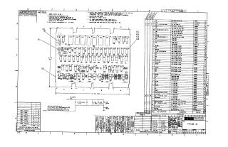
This document is a comprehensive set of technical engineering schematics for the "PROM 1K" module (Digital Equipment Corporation, 1973). The package includes:
- Assembly and Parts List: A component layout diagram and a detailed parts list (Sheet 1) identifying resistors, capacitors, transistors, and integrated circuits used on the board.
- Configuration Logic: A "Y Variation Chart" and memory mapping tables (Sheet 2) that define jumper settings and diode configurations required to customize the board for different memory field selects and starting addresses.
- Functional Schematics: Detailed circuit diagrams covering:
- Control Logic (Sheet 3 & 4): Logic for starting addresses, field selection, and memory control timing.
- Memory Array (Sheet 5): The primary ROM (1702A) organization and decoding logic.
- RAM Expansion/Interface (Sheet 6 & 7): Logic for interfacing the module with RAM and managing data pathways.
The schematics utilize standard logic gates (such as the 7400 and 8881 series) to facilitate programmable read-only memory (PROM) operations within the system.


Site structure and layout ©2025 Majenko Technologies