Installing the MXV11-B2 ROM Set on the MXV11-B Multifunction Module
Order Number: EK-MXVB2-IN
These documents provide instructions for installing the MXV11-B2 ROM set on two different modules: the MXV11-B Multifunction Module and the MRV11-D Universal PROM Module.
General Installation Steps (Common to Both Modules):
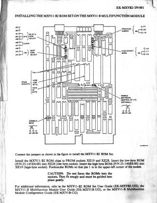
- Jumper Configuration: Users must first connect the jumpers as indicated in the respective figures for each module.
- ROM Identification: The low-byte ROM is Part Number (P/N) 23-145E4-00, and the high-byte ROM is P/N 23-146E4-00.
- Orientation: Pin 1 of each ROM must be positioned in the upper-left corner of its designated socket.
- Caution: Do not force the ROMs into the sockets; they should fit snugly and be guided gently.
Module-Specific Details:
- For the MXV11-B Multifunction Module: The low-byte ROM (23-145E4-00) is inserted into socket XE28, and the high-byte ROM (23-146E4-00) into socket XE19.
- For the MRV11-D Universal PROM Module: Both ROMs are installed in chip set 7. The low-byte ROM (23-145E4-00) goes into the LO BYTE 7 socket, and the high-byte ROM (23-146E4-00) into the HI BYTE 7 socket.
- Note for MRV11-D: MXV11-B2 Boot ROMs are 8K×8 devices; therefore, 2716 (2K×8) devices cannot be used on this array.
Both documents recommend referring to their respective user guides or configuration guides for additional information.
Site structure and layout ©2025 Majenko Technologies