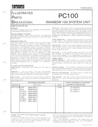
Digital PDFs
Documents
Guest
Register
Log In
EK-SB100-IP-003
2000
86 pages
Original
40MB
view
download
OCR Version
72MB
view
download
Document:
PC100 Rainbow 100 System Unit Illustrated Parts Breakdown
Order Number:
EK-SB100-IP
Revision:
003
Pages:
86
Original Filename:
OCR Text
HOW TO USE THE IPB ECO Cut-ln — The notation at the top of this column indicates the ECO level of the system {option}, at which theIPB was m«mm of the engineering drawing structure. prepared. Subsequent ECOlevel designations, that modify existing MAJOR ASSEMBLY LOCATOR column next to the part that is added or modified. A bracket ([) £ This IPB is compiled following the organization and nomenclature parts or add new parts to the device, are inserted in the ECO Cut-In The Major Assembly Locator (first illustration) s an index that provides a description and a figure reference for all illustrations used in this manual. preceding the item description is used to indicate the parts affected by ECO's. Vendor Code/Part No. — Indicates vendor parts that are not stocked by INDENTED PARTS LIST This manual identifies each assembly being broken down (figure reference callout), and all parts of that assembly. Further breakdown of an assembly is shown by an asterisk {*) preceding the item callouts in the Description Column. The number ot asterisks preceding an itemn is used to denote the subordination of that item with respect to the Major Assembly. A single asterisk preceding an tem description indicates that the item is part of the major DEC. Refer to the Field Service Spares Catalog (vendor part number to DEC part number) for the vendor code cross-reference. Used On Code — Letters in this column correspond to the variation codes assigned in Figure 1. Parts with an Alpha notation{(s) are used only in those option variations. A blank indicates that the part is used on all option variations. Ret Fig No. — A cross reference between illustrations. For each Major Assembly, the number in this column denotes the figure of w%%mw the related single asteriskitem. Additional asterisks are used, as required, to denote further subordination. This system of part column denotes the figure showing additional detailed breakdown. s mwfi%m’%mw being illustrated. Items that are subordinate to single asterisks items, are denoted by two asterisks (**) and immediately the next higher assembly. For all subassembilies, the number in this identification, provides a means for the user to identify the next higher assembly item and make alternate selections for parts when the required replacement part or assembly is not immediately SYMBOL USAGE available, number callouts on the illustration when stacked itermn numbers are Hardware Designators — Alpha designators for screws (S), washers (W), nuts (N}, and retaining rings {R) are inserted after the item used. COLUMN CALLOUT DESCR ”WWWM Figure & ltem - Indicates the figure number and item number of Attaching each part, that is used as attaching hardware. Attaching hardware is denoted as Hardware — The @ symbol s inserted before any part those parts that are not an integral part of the referenced assembly. Lists the name of the part and pertinent Description specifications (when required). Asterisks preceding the description {(NFR) Not Field Repairable — The (NFR) symbol is inserted after denote the subordination of thepart to the next higher assembly. any assembly that is not 10 be field dismantled. DEC Part No. -~ Lists the DEC part ordering number. A blank in Other Symbols — Any other symbols this column indicates a DEC part number was not assigned at the accessories, etc., will be explained and appear as part of theitem time of publication. description, PRINTING | ECO LEVEL DATE that are required for kits, TO SUPPORT THIS OPTION . ... . .. 3rd W%m%wh@mmm 00005-00010 BAZ2ZbH 00000-00002 EK-VR201-IP 70-19974 00003-00006 EK-LK201-1P 70-19573 00000-00002 H7842 00006-00013 70-19941 00001-00001 1-25-85 Copyright© 1983, 1984, 1985 by Digital Equipment Corporation. All rights reserved. DEC reserves the modifications in manual and EK-ORX50-IP DEC s not responsible for errors which may appear in the technical description (including illustrations and photographs) of the products right, without notice, to make substitutions and the specifications of products documented in this further reserves the right to products from the market without notice. withdraw any of these covered by this manual, None of the granting of any descriptions license contained in this manual imply the whatsoever to make, use or sell equipment constructed in accordance therewith, Prinnted in US4 VR201 MONOCHROME MONITOR SEE VR201 IPB EK-VR201-1P PC100 RAINBOW 100 SYSTEM UNIT SEE FIGURE 1 LK201 KEYBOARD SEE LK201 IPB EK-LK201-iP PC350-00 Rainbow 100 Basic System Configuration Frontispiece v go m,.m m»f‘%&%"m“w -:j:‘ gl s \:m,\‘«i;::%‘‘uf‘\v% g,ww- w-~/«~.§w<\rm§w g '«» e ib g g i, S i M““ e s, P G S, o,W 0 i, s,o s, i b, 5 m% w i {f“@&@ j“mww,%{mw&«mw,“% Wj~:m w%:: g, % o P S U o p- iS i M‘”m S my-“, W, “‘m “"w‘\“w S T e W“M‘% m,:m:“j“'wf““%*mm» o Sagg S, o ““‘w “‘m"%“ o x\.,jm S% P P,oy i o Suffjm ”m,f‘”w.f% ““««w, o ?:‘”*’»A‘, g o, vNM‘M " g " iy oy S s, A i, P g, S i g i g s, s e % g ‘MWi " Uy),M e S, om MKN A o %v%%%w?m i S, N o ~\no iy ~x, gi S . /» ”"»», % i w“mj‘% M,% \)MMUWN,“M;W’\Na.‘fl”‘w“:»mw L i V‘w ‘ i “*wg W % "«%fi g Vi 5, flw‘%“r’“ i iW g w i g“Miy g wjjm,Vi ""»\MM g i Nj‘v . %g »«’ m,w i, 2 io wM,‘,i iy, Sy ”’w -i i “’m % “‘“2:3%w'Wmh i w g i S iy wwfl%mY, w\f““'« s S 3, “*‘Mw’””w“”% s, s, it o, w% Mo,h,,," - % e o v«% m S % i o N N i “w g S S ew« w‘ “’w ww g g g, g Wi N So )Ri aw, g S o, N i o%% M,M.M i i ‘,“ m“‘m B 'wa,‘ g Pl m,%i i m m mfi ».% ‘ '«z% u‘i““w “w m%w, i Me% “u\,,,, @M‘\m%,‘Vi ‘%M "y i, M% Vo, w%»,,%‘“w.:*w g, m’“«‘ i b i, oo, m g w,h:“w”‘% W%f“ o %‘“*mw“\“‘“ oogt ' »\%m, e i P g % i»N %‘% o %,,‘,fim“’“fi“ S j« b“m “'MV«m,%n.w” g 2 »(%M%“m e m..%\\ "NMo w S”‘w ‘M i \m“ R o %:A%"um%Mfi\% i i, o M o o ’”M,”‘M’T’“v«%‘«fis o,«nm “‘wj'"\w,“"“ i o g g i ity P, O g M ”w »““ ,‘M '(n,fl Vo o o,e g i Vi, e L g, ‘\xHM s, " G i A . M"A‘” i "\m\% “&W“i ”‘%.W‘WMM g % «‘ e o \%m\( & . A iy o b B, m m \% i Nm\\%%\) S y ‘u,, T i g L«m wWM w,“w“ww i Nn““ om,,«\m g e S i N'“'»x wesi“' i uf““M "’*’% S,%"NM""‘%‘W\““’w”m g g i i g o W;m i, S %,wmwy i»,,sN o A"”V«“""\y ““‘%,N‘ oS & o i i “v« “”'w w “‘w”m,’"‘m,ol o, .m‘* e S A m. gty gy Y Mm‘w«,\ SERNEREY B S ’% m' w e w w;wfi S i, W‘\ e o L iy N% Ny ? w fm o, ||P i i ]! %3;% (a,:« e M\N s ey "'"m i e ”w «.MMs g “‘H«,“ o S B % S imm%fl‘;&wm gt mm’ i i P . i, io, g g, e o "“"wm i i ‘mwmw W PC100-01 IPB-PC100 —— | PARTS LIST ) ", "y o B e “@“s S % 2 "N: W w e PC100-01A L IPB-PC100 b Figure 1. PC100-A Rainbow 100 (Sheet 2 of 2) FIG. | | & F | lTEM ' | NO. | T— X~ X— _DESCRIPTION PART NO. | 2] Code A — Used on Model PC100-A, 120/240V PC100-A Code B — Used on Model PC100-A1, 120V (added) PC100-A1 *SYSTEM UNIT ENCLOSURE ASSEMBLY *SYSTEM UNIT ENCLOSURE ASSEMBLY (added) BAZ25-B *CPU ASSEMBLY 70-19974-00 (NFR) See Note Below BA25-A 3] *RX50 Controller Module 54-15482-00 41 “Medallion {Rainbow) X— 5} TMSpring, Compression 74-27256-03 12-20113-01 X— 6] *Video Cable Assembly (6 ft) X— 71 "RX50 DUAL DISKETTE DRIVE (added) 8] X— CUT-IN | PC100 |USED ON oppos | € PC?@@»A WMN%@W mm 1] X— DEC ECO A 00006 B A 00006 B 2 2 3 17-00283-00 See RX50 IPB| RX50-AA 00006 B “H7842-B POWER SUPPLY 120V (added) H7842-B 00006 B 9| “Communication Cable Assembly (BCCo4) (10 ft) (added) 17-00402-01 00010 10| *Printer Loopback Plug 29-24631-00 11| "Comm Connector Loopback Plug 12-15336-01 6A Labels (Not Shown) *Label, "’Regulations"” 36-20218-01 *Label, “"Regulations” (added) 36-20218-07 * Label, “Power Rating”’ A 00006 36-20215-06 *Label, “"Power Rating” (added) *Label, “Bar Code”’ 36-20215-08 00006 B 36-16157-00 36-21750-01 00006 A B 36-18460-06 * Label, “Correct Voltage Setting'’ *Label, “Permanently Set for 120V’ {added) B A Note; NFR=Not Field Repairable X = Purchasable Parts from PSG (See Green Section) 3 3/4 IPB-PC100 PARTS LIST wwmm . ”‘m,% «w o i i, o @ L'N‘», %«:‘%” 5 o ML“W%“‘»f\;:’ om‘.j"m g“w-.“‘% P w-m g\w\,,%‘ g w\,% .M:%G ,m:»«,%g gw“m"m iy NN y ‘"”“’/C“‘M‘*m i ‘o“mn g,”M’ it g "«4 s,8 LV ‘m“m‘ i oo S o i ,:,,4 S,m g S W ’m“\w“}s - e o g o -0 ’m" ! \s "Q(‘”‘Sv« o wN «\,’w i, m o oi, « w% o, s o%\m % s, i ‘“” gu,:“’«“’”* ey m ”’w o L i, B s, H’wws o, o g m'm «“w s m:m,,m ‘M,’wk Ry mfi”w I gi S o ew% e i A o o ”\/,‘.,“ . . Nn o \‘«W%,k o et S\‘Wf;“‘w o i P Mo o i 5v “%""Q“wm“«» w, i ««, g “;t o i “‘4 o "mfw“w ot “" ‘ ‘ b e “ . o ei o m. “M e «%m« e m "‘N“Wr P N el , ,,% W\) Sw S o o o ft fw oi i S . ww e% .oy b o w%‘;\% i, Wh o o g Mty st eStg L g, B Fing e '“w& ““w '»w, o “mi v,q s g mmwwfl)m e «/M e i p—— WW‘M W WW“— wwm,mm i i, 'w S g, i,y ”‘m‘,"&"‘ ‘./‘\:v L% iy L i,Mm PC100-01B Figure 1A. PC100-B Rainbow 100 {Sheet 1 of 2) 5 iPB-PC100 PARTS LIST PC100-01C Figure 1A. PC100-B Rainbow 100 (Sheet 2 of 2) iPB-PC100 6 3 FIG. & | Pcioo |USEDON| FIG PART NO. | 00010 | DEC NoO. UESWWT&QM 1A Eco | WEM | T | CcuT-IN ] | REF CODE | NO. WQZW@ % %’MW%@W 100 Code C — Used on Model PC100-B2, 120V, PC100-B2 C PC100-B3 D PC100-B4 E PC100-B5 F PC100-B6 G PC100-B7 H (NFR) See Note Below BA25-CB 70-19974-02 C~-H C, D 2A 3B *CPU ASSEMBLY (NFR) See Note Below *CPU ASSEMBLY (NFR) See Note Below 70-19974-03 70-19974-04 E 3B 3B English, German, French Code D — Used on Model PC100-B3, 240V, English, German, French | Code E — Used on Model PC100-B4, 240V, English, Dutch, French Code F — Used on Model PC100-B5, 240V, English, Finnish, Swedish Code G — Used on Model PC100-B6, 240V, English, Danish, Norwegian Code H — Used on Model PC100-B7, 240V, English, Spanish, ltalian X— 11 *SYSTEM UNIT ENCLOSURE ASSEMBLY 2] *CPUASSEMBLY (NFR) See Note Below 70-19974-05 F G *CPU ASSEMBLY (NFR) See Note Below 70-19974-06 H *RX50 Controller Module 54-15482-00 *CPU ASSEMBLY X— 3| 41 *Medallion (Rainbow +) 74-27256-06 X— 5| *Spring, Compression 12-20113-01 X— 6| TMVideo Cable Assembly (6 ft) 17-00283-00 7| *Motherboard Cable Assembly 17-00318-02 X— 8] *Communication Cable Assembly (BCC04) (10 ft) 17-00402-01 9! *Printer Loopback Plug 29-24631-00 10} *Comm Connector Loopback Plug 12-15336-04 3B 3B Labels {(Not Shown) * Label, ”m@mmm” 36-20218-09 *Label, “’Regulations” C, E-H 36-20218-12 *Label, “Power Rating” D 36-20215-09 *Label, ““Bar Code”’ *Label, “Correct Voltage fimmg *Label, “Correct Voltage Setting 36-17905-07 36-17905-09 * Label, ““Correct Voltage Setti m; D, H 36-17905-11 *Label, “Correct Voltage Setting” F, G 36-17905-12 E 36-18460-06 C Note: NFR=Not Field Repairable X = Purchasable Parts from PSG (See Green Section) 3 7/8 IPB-PC100 | wfi“:s, et M ‘ %Q‘“ »" 2 ag«, o ", o, ., "\a % s -.W” e v M(%W »N,MWN»,,W s ”“w m“» "\'v'”“wo i A m%‘w m g e ej‘m:w;%m ‘w ot i g S, [ 5 . ‘:«, W““m i ”w“‘“ % &“‘ s¢w_w ”%%\%““ e M‘“’ ww :wqwf:u-m;; eo . : M wwmgt . “‘:nB”-J”“«"’ “w:: M,%::WKI;:“"«W M,fi:f B m;:fl%:‘“_‘ %" P B, e, o S S, [ m:mBw;::»:%w i S, ee e Sy w e o “»» Q MM,\g:‘Wg‘“m%m%fi%;«a\m,:»«‘,f%. N,).“m ‘,.% i %,“u < i, iymm M, ‘”\\, i ii i ; ”%“, %w‘ i 6 . % “w ot m"« w ‘m % e g o Ro a, B %o,\J' %;;%% w e MT o g ‘m "‘%‘ i is,g . v% y wfl 5 o e 5 P o'“M( T Q“-“%ot w\_w ‘W‘, % o e s i~ ‘j«u\)mw i " N ”‘m ‘m"‘m‘“» o DN w« i ‘w B o s o o o i, e :\m sm\S, , tlo, N:W.%M‘v L e M.‘w' i i i, o ‘uoo iy% m”m g, %‘wg g m~g, H\\iy S i i M Py 1 A“m\ i i, “m iw R i, S i %.i, i i i*“w”“" it%mer.%xl \%;\ My, * ggmm% w,, ; g "w i M‘w"'wL o »‘, o “‘wg ,’jyf”“»-l“‘m“L“‘w S, i- g 0 ,. it,:::W“ »\“‘o S .(,‘ e m w"w ‘\m o o M’“i, ‘«;‘, e ‘m S i oy % . e g w,,\ M "‘“::;“%J‘% i g V'm“” i g, i %M% B ‘W,;"w, Mi r%w& B g P me e i ”“‘ i, i i P m ”% fi ”'A i, i, '“M“w ‘u Py m . “w‘,‘, - M“‘Y‘V““W‘”«vw g s e m“«\«w 4 e oN, et M"‘MM /. m% fl'«%" PC100-02 G Figure 2. PC100-A System Unit Enclosure Assembly (Sheet 1 of 2) IPB-PC100 PARTS LIST PC100-02A Figure 2. IPB-PC100 PC100-A System Unit Enclosure Assembly (Sheet 2 of 2) 10 3 | FIG. | _& | | 'TEM | j ~ 2 - | | PART NO. | 00000 DEC SYSTEM UNIT ENCLOSURE ASSEMBLY (added) BA25-A | Ba2s | REF | |usepon| rig | CODE | NO. § *BOTTOM ENCLOSURE ASSEMBLY 70-19573-00 *Screw, Phl Flat Hd No. 6-32 x 5/16 90-06021-02 *FAN BRACKET ASSEMBLY 70-19572-00 90-09701-00 See RX50 IPB *H7842-A POWER SUPPLY (deleted) (See Note) oo X *H7842-D POWER SUPPLY (added) *Motherboard Cable Assembly (deleted) RX50-AA H7842-A H7842-D 17-00318-01 17-00318-02 “Cable Assembly 17-00317-03 *Clip, Flat Cable *Top Enclosure Assembly *Plate, Cover Bezel 12-13715-02 = 9] OO *Motherboard Cable Assembly (added) RS 00001 *Riveted Assembly *RX50 DUAL DISKETTE DRIVE X — X — | CUT-IN | DESCRIPTION *Screw, Sems Phl Pan Hd No. 6-32 x 5/16 X— ECO | SYSTEM UNIT ENCLOSURE ASSEMBLY RS b X— Bl | Note: 70-19505-01 74-26788-10 H7843-A is an acceptable alternate for BA25-B variation. IPB-PC100 ”m.o i1, i iS, i i, “M,‘W £z wV‘“w‘"yufi“}o e “’m5 w’moi ,% N %\‘%\W " %w,\"m o s of“\m, m‘w“"‘v lemuw“t/g [i % i, o e o ’M,N””Wg, %, :-« e ii 2 s o,g CH. g g o Lol s i o “w K ew“‘w = @W i w % M imww‘ i“‘“m,‘w i ’% % ‘*w”w‘,” T Nl m S, s 5 i m %M““M‘”‘:L“M~w‘~ m’«,u"»\,,\ g M SS, Q“m.@mw% i o owv,,vu“’w\ ) e - MS i, m m,“wf‘“m i 5, e oi W e f”m”‘* ee o L e u%\% mwwv M w” Q« b " “"m““w»m so . et eS iy s fi».\“”'v«.(;;m iy m(”‘«y g -o St w«,.‘:mwm,;'m e "‘”N“‘“‘w i i i g i g o s v“:u\\‘“w, g g i i ) w. M%“ "'m,j:m,“% i, i & MMMQ»VM;% ie ‘“m‘“m“‘“% S w S s, i e g g em,»,“M gs Vi, P s‘WQ"“«»':” % .qw o ev‘“m’w.‘ I ) e %“W«s, “w""\\ g ’%\,,“»M«, ot ”‘w\ gs i s B ‘mi %w( e 5 v\“\m“‘w»j%.« ot Wi g s, ; e Y% ” ww‘Me “*m:m‘i““m“w:‘m;h s o s w\m, m?wi o, S T %WWB S o SS %,"‘m’w?““m‘m?“moy ‘w““w « ! m,,‘M“’“m“% 2o"" BS~1 s, g i et r, i “w \ »,m i i O, \, i s oti, e, @ i i o M o.H‘“w,"%w,%"lw i e ‘m‘m g ii BB, i, i Pg b o i oi, S sB B 5 “‘wi“‘w m’%;g Nw“m o o o“w"”"‘mi gk M e, i isW%«QW S, g g ‘M i ‘wiy i ,“m‘w i \“\ B “mt,"‘m o w/w e G Gi il Sy ”*ml"‘ ey e «\\ e b, o S Sy e o sw‘hfmlm b g L",“«w B “m ’%'} ey Wi %w “'m ‘“12*’ S i e A ‘v"“ o N\.% i S, PC100-02B Figure 2A. PCT100-B Systern Unit Enclosure Assembly (Sheet 1 of 2) 13 IPB-PC100 T S LIS PART PC100-02C Figure 2A. IPB-PC100 PC100-B System Unit Enclosure Assembly (Sheet 2 of 2) 3 FIG. ECO DEC DESCRIPTION | . QWO <O O & WK - X X b : > i £ i 2A— | PART NO. SYSTEM UNIT ENCLOSURE ASSEMBLY BA25-CB *BOTTOM ENCLOSURE ASSEMBLY 70-19573-00 *Riveted Assembly 70-19571-01 *Screw, Phl Flat Hd No. 6-32 x 5/16 90-06021-02 *FAN ASSEMBLY *RX50 DUAL DISKETTE DRIVE BA25. 00002 |USED ON| FIG | | - CODE | ” 70-20816-01 See RX50 IPB RX50-AA *H7842-D POWER SUPPLY H7842-D *Cable Assembly 17-00317-03 *Clamp, Cable (Adhesive Mount) 90-09771-03 *Top Enclosure Assembly & NO. | O ITEM | CUT-IN BA 70-19505-01 *Screw, Sems Phl Pan Hd No. 6-32 x 5/16 90-09701-00 X = Purchasable Parts from PSG (See Green Section) 3 15/16 iPB-PC100 FIG. | | | 1ITEm | || & | [ R DESCRIPTION - 70-19974-00 *System Module Assembly 54-15486-01 *Support, Keel 74-27719-01 *Screw, Phi Pan Hd No. 4-20 x 3/16 90-1C411-01 *CONNECTOR PANEL ASSEMBLY *Washer, Flat *Screw, Phl Pan Hd No. 4-40 x 5/16 “Screw, Sems Phl Pan Hd No. 4-40 x 5/16 *Washer, Ext. Tooth Lock 70-19941-00 REF | |USED ON| FiG CODE | NO.| A, B 90-09948-00 90-06010-01 90-00049-44 90-10099-00 *Screwlock (Standoff Only) 90-08451-05 *Locktite Adhesive 90-09321-00 *Standoff 12-19857-01 *Clip, Restraint *Clip, Retainer {added) 74-28524-01 Note: Eco | cuT-IN DEC | 7019974 PC100-A CPU ASSEMBLY (NFR) See Note Below * Hl Y 74-28702-02 {(NFR)=Not Field Repairable X = Purchasable Parts from PSG (See Green Section) PC100-03 Figure 3. PC100-A CPU Assembly 17/18 1PB-PC100 [FiG. gM DEC | NO. WOR 0T D PC100-B CPU ASEMBLY (NFR) See Note Below 70-19974-01 *System Module Assembly *Support, Keel 54-16206-01 - 70-19941-00 *Washer, Flat 90-09948-00 *Screw, Phl Pan Hd No. 4-40 x 5/16 90-06010-01 *Screw, Sems Phl Pan Hd No. 4-40 x 5/16 90-00049-44 *Washer, Ext. Tooth Lock 90-10098-00 *Screwlock (Standoff 90-08451-05 On *Locktite Adhesive | CODE 3B = 12-19857-01 B 90-09321-00 *Standoff *Clip, Restraint 74-28524-01 *Clip, Retainer 74-28702-02 Note: REF | | USED ON| FIG 74-27719-01 *Screw, Phl Pan Hd No. 4-20 x 3/16 *CONNECTOR PANEL ASSEMBLY L OO 00~ § }{ ps % | PARTNO.| goo0s DESCRIPTION X—3A— mU“y’" (NFR)=Not Field Repairable X = Purchasable Parts from PSG (See Green Section) PC100-03A Figure 3A PC100-B CPU Assembly 19/20 IPB-PC100 DEC D&%GWPWQM = REF | USED ON| FIG C, D TA 00006 PC100-B CPU ASSEMBLY (NFR) See Note Below B CUT-IN 70-19974 PC100-B CPU ASSEMBLY (NFR) See Note Below 70-19974-03 E 1A PC100-B CPU ASSEMBLY (NFR) See Note Below 70-19974-04 F 1A 1A PC100-B CPU'ASSEMBLY (NFR) See Note Below 70-19974-05 PC100-B CPU ASSEMBL Y (NFR) See Note Below 70-19974-06 H 23-020E5-00 C,D *CPU ASSEMBLY *ROM 1 CLUSTER 1 (English, German, French) *ROM 1 CLUSTER 2 (English, French, Dutch) *ROM 1 CLUSTER 3 (English, Finnish, Swedish) 23-016E5-00 F *ROM 1 CLUSTER 4 (Ewhm Danish, Norwegian) 23-017E5-00 G “ROM 1 CLUSTER 5 (English, Italian, Spanish) 23-018E5-00 Note: (NFR)=Not Field Repairable X = Purchasable Parts from PSG (See Gareen Section) PC100-03B Figure 3B. PC100-B CPU Assembly iPB-PC100 F!\GW ECO CUT-IN 70-19573 DESCRIPTION PART NO. X—4— BOTTOM ENCLOSURE ASSEMBLY 70-19573-00 *Enclosure, Bottom 74-26688-01 X *Latch, Wire {(R.H.) 74-26242-01 *Latch, Wire (L.H.) 74-26242-02 )o *Handle, Latch Wire 74-26537-01 * Adhesive 49-01259-00 | *Washer, ))))) i X— 9 90-09775-00 Flat (delet ed) I"Washer, Flat 2,2A 90-09775-01 (added) *Spring, Compression *Ring, Retaining 90-09273-00 *Bumper, Rubber {Adhesived Backed) 90-08525-00 12-19914-01 X = Purchasable Parts from PSG (See Green Section) PC100-04 Figure 4. Bottom Enclosure Assembly 23/24 iPB-PC100 FIG. ; o | ECO ITEM | no. DEC | DESCRIPTION 70-19572 | USED ON i S 5 K PC100-A A.C. FAN BRACKET ASSEMBLY 70-19572-00 *Bracket, Fan 74-26691-01 “Fan, 4-1/2 in. 70 CFM 12-13185-03 *Guard, Finger 12-10263-01 *Screw, Phl Pan Hd No. 6-32 x 7/8 *Washer, Flat 90-06027-01 *Nut, Kep No. 6-32 90-08185-00 A,B 2 90-06653-00 X— *Switch, Rocker 16A 12-17051-04 X— *Bezel, Switch 74-26246-01 *Fan and Switch Harness Assembly *Washer, Ext Tooth Lock No. 10 90-07651-00 *Nut, Kep No. 10-32 90-06565-00 *Bushing, Snap (Nylon) (added) 00001 *Cable Tie (added) 90-07880-00 X = Purchasable Parts from PSG (See Green Section) PC100-05 A.C. PC100-A Fan Bracket Assembly 3 25/26 IPB-PC100 PARTS LIST / - PC100-06 Figure 6. 3 H7842-A Power Supply 27 IPB-PC100 ECO | ITEM| DESCRIPTION DEC CUT-IN H7842- PART NO. 00006 | USED ON] | cope b X—6— H7842-A POWER SUPPLY (deleted) (See Note) H7842-A A 00001 *Box, Power Supply 74-26693-01 *Power Supply Board 54-15187-00 *Support, PC Board 12-20330-01 *Screw, Phl Pan Hd No. 6-32 x 3/8 (Tapping Type) *Line Filter Assembly 90V @ 4A Ko X— *Screw, Sems Phl Pan Hd No. 6-32 x 5/16 *Circuit Breaker 4.0A 250V 90-10155-00 *Nut, Switch No. 3/8-32 90-07628-00 *Washer, Ext Tooth Lock No. 10 90-07651-00 *Nut, Kep No. 10-32 90-06565-00 12-19912-02 *Screw, Phl Pan Hd No. 6-32 x 3/8 90-06022-01 *Screw, Washer Pan Hd No. 6-32 x 5/16 90-10245-00 *Jumper Cable Assembly 70-19522-00 *Floppy Drive Harness Assembly 70-19730-00 *Cable Tie *Bushing, Snap (Open/Close) 90-07880-00 *Cover, Power Supply 74-26692-01 90-10353-01 Labels/Decals {Not Shown) 36-20123-01 36-16157-00 36-20124-01 *Label, ““Fuse” * Label, “Caution, Correct Voltage Setting’’ *Label, “Caution” *Decal, l “Ground”’ 36-20122-02 I “Electrical Rating” *Label, Note: H7842-A is an acceptable alternate for the PC100-A variation. X = Purchasable Parts from PSG (See Green Section) 1PB-PC100 28 | P i s Figure 6A. H7842-B/D Power Supply Aymmi:»ly “l % QY O O0CO~NOO AW BWN = ! § > CUT-IN | PART NO. 00013 | DEC DESCRIPTION Eco ) H7842. |USED ON| CODE FIG NO. H7842-B POWER SUPPLY ASSEMBLY H7842-B B 1 H7842-D POWER SUPPLY ASSEMBLY H7842-D A, C-H 2,2A *Box, Power Supply 74-26693-01 *Power Supply Board 54-15187-00 B *Power Supply Board 54-15187-01 A, C-H *Support, PC Board 12-20330-01 *Screw, Phl Pan Hd No. 6-32 x 3/8 {Tapping Type) 90-09755-00 *Line Filter Assembly 90V @ 4A 70-19732-00 *Serew, Phi Pan Hd No. 6-32 x 1/4 90-06020-01 *Circuit Breaker 4.0A 250V 12-19912-02 *Nut, Switch No. 3/8-32 90-07628-00 *Washer, Ext Tooth Lock No. 10 90-07651-00 *Nut, Kep No. 10-32 90-06565-00 *Screw, Phl Pan Hd No. 6-32 x 3/8 90-06022-01 *Screw, Washer Pan Hd No. 6-32 x 5/16 90-10245-00 *Jumper Cable Assembly 70-19522-00 *Floppy Drive Harness Assembly 70-19730-00 B *Floppy Drive Harness Assembly 70-19730-01 A, C-H *Cable Tie 90-07880-00 *Bushing, Snap (Open/Close) 90-10353-01 *Cover, Power Supply 74-26692-01 *Plate, Voltage Switch Cover 74-28933-01 B *Label, “Fuse” *Label, “Caution, Correct Voltage Setting” 36-20123-01 36-16157-00 A, C-H * Label, “*Caution”’ 36-20124-01 Labels/Decals (Not Shown) *Decal, ""Ground”’ 36-12680-02 *Label, “Electrical Rating’” 36-22148-00 X = Purchasable Parts from PSG (See Green Section) iPB-PC100 REF 30 PC100-07 Figure 7. 3 D.C. Fan Bracket Assembly 31 IPB-PC100 | A FIG. ECO & | ITEM NO. PART NO. DESCRIPTION PC100-B D.C. FAN BRACKET ASSEMBLY | X—7— CODE (added) a0 R s 00001 *Bracket, Fan 74-29088-01 *Fan, 4-1/2 in. 40 CFM 12-21817-01 *Guard, Finger *Screw, Phl Pan Hd No. 6-32 x 7/8 *Washer, Flat 90-06653-00 *Nut, Kep No. 6-32 90-08185-00 *Switch, Rocker 16A *Bezel, Switch X — T *Fan and Switch Cable Assembly *Washer, Ext Tooth Lock No. 10 *Nut, Kep No. 10-32 *Cable Tie X = Purchasable Parts from PSG (See Green Section) iPB-PC100 NO. Bl | PART NO. ECO | CUT-IN | 00001 | CODE OO B WN - i *Weldment, Connector Panel 70-19943-00 *Panel, Filler 74-27174-01 *Panel, Dress 74-26678-01 90-00003-05 *Washer, Flat *Ring, Ext Retaining 12-20908-01 *Screw, Thumb 74-27703-01 *Screw, Phl Pan Hd No. 4-24 x .22 (Self Tap) 90-10426-01 *Label, “Use Coin To Turn” 36-21104-01 { = Purchasable Parts from PSG (See Green Section) PC100-08 Figure 8. Connector Panel Assembly PC100 OPTIONS _1bmf_iahu_Sloikl i Ll Ll i I hrtL_e<t%1 KB, i"e _. ! flL " \ o i k i Hebpird PARTS LIST . Ny ';6!4 'fi REFERENCE RX50 CONTROLLER MODULE L . STANDOFF PC100-09 . Figure 9. PC100 Options (Sheet 1 of 4) 3 A-1 IPB-PC100 dlijgiltiall PARTS LIST l , REFERENCE S RX50 CONTROLLER MODULE : 2 - 6 STANDOFF PC100-09A Figure 9. PC100 Options (Sheet 2 of 4) IPB-PC100 A-2 I e PARTS LIST REFERENCE RX50 CONTROLLER MODULE PC100-A PC100-09B Figure 9. 3 PC100 Options (Sheet 3 of 4) A-3 IPB-PC100 PARTS LIST REFERENCE RX50 CONTROLLER MODULE PC100-B PC100-09C Figure 9. IPB-PC100 PC100 Options (Sheet 4 of 4) A-4 3 ECO DEC DESCRIPTION PART NO. = 9— | CUT-I 5 REF USED ON| FIG - “CODE —— NO. — PC100 OPTIONS Code X — Used on Models PC100-A, PC100-A1 PC100-A X Code Y — Used on Models PC100-B2, PC100-B3, PC100-B Y PC100-B4, PC100-B5, PC100-B6, PC100-B7 1 | YEXTENDED COMMUNICATION OPTION PC1XX-BB 12 1A | *PC100-A WINCHESTER DISK OPTION 13 *PC100-B WINCHESTER DISK OPTION 14 2 | *"MEMORY ADAPTER OPTION (See Note 1) PC1XX-AK X % X— 3 | *64K Memory Board PC1XX-AA X= *192K Memory Board PC1XX-AB X p 22 *128K Memory Board PC1XX-AC Y X~ *256K Memory Board PC1XX-AD -3 4 | *64K Add-on Memory Chips PC1XX-AY Y Y 10 *256K Add-on Memory Chips PC1XX-AZ 5 | *COLOR GRAPHICS OPTION PC1XX-BA 15 6 | *NUMERICAL DATA CO-PROCESSOR (8087) PC1XX-EA 11 (See Note 2) 7 | *TECHNICAL CHARACTER SET PC1XX-FA X 8 | **Label, ‘’Special Option Installed"’ 9 | *TECHNICAL CHARACTER SET 0 | **Label, “Special Option Installed” 36-23792-01 PC1XX-FB 36-23792-01 e Note 1: The Memory Adapter Option allows the use of additional memory options on the PC100-A. These options are: PC1XX-AC, PC1XX-AD, PC1XX-AY, PC1XX-AZ. These are normally : used only on the PC100-B. The above memory options (ltems 3, 4) can only be used on the PC100-A by using the Memory Adapter Option or the Numerical Data Co-Processor (See Note 2). Note 2: The Numerical Data Co-Processor (NDC) can be used on either the PC100-A or PC100-B. When the NDC is installed, any Rainbow memory may be used (PC1XX-AA, PC1XX-AB, PC1XX-AC, PC1XX-AD, PC1XX-AY, PC1XX-AZ). X = Purchasable Parts from PSG (See Green Section) S A-5/6 IPB-PC100 _1bmf_iahu_Sloikl i Ll Ll i I hrtL_e<t%1 KB, i"e _. ! flL " \ o i k i Hebpird PARTS LIST 3 STANDOFF ENGAGES HOLE IN ADAPTER BOARD 2 1 MEMORY BOARD 5 /7 - 2 3 / 5 ; e ‘ MEMORY \ = = / 4 COMPONENTSIDE DOWN BOARD PC100-10 Figure 10. 3 Memory Adapter Option A-7 IPB-PC100 ECO CUT-IN DEC T S T X—-10— USED ON PART NO. DESCRIPTION MEMORY ADAPTER OPTION (See Note) CODE e P . M 3/ AT T e PC1XX-AK 1 *Memory Adapter Board 54-16535-01 2 *Clip, Module Board Spacer 74-30494-01 3 *Insulator, Memory Board 74-30512-01 4 *Puller, Chip 74-30612-01 5 *Cable Assembly *MUP Diskette (Not Shown) BL-T905A-BV, 6 Note: 17-00662-01 The Memory Adapter Option allows the use of additional memory options on the PC100-A. These options are: PC1XX-AC, PC1XX-AD, PC1XX-AY, PC1XX-AZ. These are normally used only on the PC100-B. The above memory options can only be used on the PC100-A by using the Memory Adapter Option or the Numerical Data Co-Processor. X = Purchasable Parts from PSG (See Green Section) IPB-PC100 A-8 NO. dlifgliltiall PARTS LIST STANDOFF ENGAGES HOLE IN ADAPTER BOARD MEMORY 5 BOARD ‘ . ‘ = COMPONENTMEMORY SIDE DOWN BOARD PC100-11 Figure 11. 3 Numerical Data Co-Processor A-9 IPB-PC100 FIG. ECO & DEC ITEM PART NO. DESCRIPTION 11— NUMERICAL DATA CO-PROCESSOR (8087) (See Note) PC1XX-EA 1 *8087 Module 54-16535-02 2 74-30494-01 3 *Clip, Module Board Spacer *Insulator, Memory Board 4 *Puller, Chip 74-30612-01 9 *Cable Assembly 17-00662-01 6 *NDP Diskette (Not Shown) BL-DE92A-BV Note: 74-30512-01 The Numerical Data Co-Processor (NDC) can be used on either the PC100-A or PC100-B. When the NDC is installed, any Rainbow memory may be used (PC1XX-AA, PC1XX-AB, PC1XX-AC, PC1XX-AD, PC1XX-AY, PC1XX-AZ). X = Purchasable Parts from PSG (See Green Section) IPB-PC100 A-10 REF CUT-IN USED ON FIG CODE NO. - - . dlilgliltiall PARTS LIST REFERENCE RX50 CONTROLLER MODULE PC100-12 Figure 12, Extended Communication Option (Sheet 1 of 2) A-11 IPB-PC100 dlifgliltall PARTS LIST SLIDE IN AND PUSH DOWN PC100-12A Figure 12. IPB-PC100 Extended Communication Option (Sheet 2 of 2) A-12 3 ECO DEC CUT-IN USED ON| FIG PART NO. DESCRIPTION T S R T PC1XX-BB 12— |EXTENDED COMMUNICATION OPTION X— X— 1 54-15703-01 | *Extended Communication Option Module 2 | *Plate, Option 74-27175-01 3 BCC15 | *Modem Cable 4 | *Plug, Loopback 12-15336-04 5 | *Option Test Diskette (Not Shown) BL-V174A-MV X = Purchasable Parts from PSG (See Green Section) A-13/14 IPB-PC100 _1bmf_iahu_Sloikl i Ll Ll i I hrtL_e<t%1 KB, i"e _. ! flL " \ o i k i Hebpird dlifgliltiall PARTS LIST SPACERS NEEDED ON BLACK CONNECTOR ONLY; NOT NEEDED ON BROWN CONNECTOR. CONNECTOR 2 REFERENCE 5 RX50 CONTROLLER MODULE PC100-13 Figure 13. PC100-A Winchester Disk Option (Sheet 1 of 4) A-15 IPB-PC100 dlilgliltlall PARTS LIST STANDOFF CONNECTED CONNECTOR CLIP CONNECTED PRESS DOWN I REFERENCE RX50 CONTROLLER 8 9 MODULE 2 8 H AN '\/@\/- 5 3 STANDOFF CONNECTED PC100-13A Figure 13. IPB-PC100 PC100-A Winchester Disk Option (Sheet 2 of 4) A-16 3 dligiltia ) PARTS LIST PC100-13B Figure 13. PC100-A Winchester Disk Option (Sheet 3 of 4) A-17 IPB-PC100 e PC100-13C Figure 13. IPB-PC100 PC100-A Winchester Disk Option (Sheet 4 of 4) A-18 FIG. ECO DEC ITEM PART NO. DESCRIPTION REF CUT-IN USED ON - CODE ————— PC100-A WINCHESTER DISK OPTION *RD50 5 MByte Disk Drive RD50 *RD51 10 MByte Disk Drive RD51 *UPGRADE KIT PC1XX-UA **H7842 Power Supply H7842-D **Power Cable (4 inches) 17-00318-02 **Clip, Connector 74-28702-02 **Diagnostic Diskette (Not Shown) BL-W968A-MJ **Spacer 74-29790-01 *CONTROLLER ASSEMBLY PC1XX-DA **Controller Module 54-16019-00 **Cable, Controller to Drive **Standoff 74-29164-01 17-00427-01 X = Purchasable Parts from PSG (See Green Section) A-19/20 IPB-PC100 _1bmf_iahu_Sloikl i Ll Ll i I hrtL_e<t%1 KB, i"e _. ! flL " \ o i k i Hebpird dlifgliltia ) PARTS LIST PC100-14 Figure 14. PC100-B Winchester Disk Option (Sheet 1 of 2) A-21 IPB-PC100 dligiltiall PARTS LIST STANDOFF STANDOFF CONNECTED CONNECTED N R \\;3' PRESS DOWN N REFERENCE RX50 CONTROLLER o /.//0’/! / P _ob‘ < MODULE 2 5 3 PC100-14A Figure 14. IPB-PC100 PC100-B Winchester Disk Option (Sheet 2 of 2) A-22 ECO DEC PART NO. DESCRIPTION PC100-B WINCHESTER DISK OPTION RD50 RD51 PC1XX-DA **Controller Module 54-16019-00 WN *RD50 5 MByte Disk Drive *RD51 10 MByte Disk Drive *CONTROLLER ASSEMBLY ~NOoOO OB 14— **Cable, Controller to Drive 17-00427-01 **Standoff 74-29164-01 . **Diagnostic Diskette (Not Shown) BL-W968A-MJ *Label, ““100+" 36-22267-01 X = Purchasable Parts from PSG (See Green Section) A-23/24 IPB-PC100 _1bmf_iahu_Sloikl i Ll Ll i I hrtL_e<t%1 KB, i"e _. ! flL " \ o i k i Hebpird ECO DEC DESCRIPTION PART NO. 15— | COLOR GRAPHICS OPTION 1 X— PC1XX-BA *COLOR GRAPHICS OPTION HARDWARE CUT-IN USED ON| CODE REF FIG NO. 9 PC1XX-BC 2 | **Color Graphics Option Module 54-15688-01 3 | **Cable, Color Video (BCC17) 17-00284-02 2056080 X = Purchasable Parts from PSG (See Green Section) Q (@) O 1 3 PC100-15 Figure 15. 3 Color Graphics Option A-25/26 IPB-PC100 _1bmf_iahu_Sloikl i Ll Ll i I hrtL_e<t%1 KB, i"e _. ! flL " \ o i k i Hebpird ILLUSTRATED PARTS BREAKDOWN COMMENT SHEET Any and all comments and suggestions for correcting errors and/or additional information to improve this manual will be reviewed and researched for possible use when this manual is revised and/or reprinted. Enter your comments and suggestions in the form provided below and return to Technical Documentation. PC100 MODEL _RAINBOW 100 SYSTEM UNIT FIGURE NO. ITEM NO. PUBLICATION NO. FIGURE NO. CHANGE FROM CHANGE FROM CHANGE TO CHANGE TO FIGURE NO. ITEM NO. FIGURE NO. CHANGE FROM CHANGE FROM CHANGE TO CHANGE TO FIGURE NO. ITEM NO. FIGURE NO. CHANGE FROM CHANGE FROM CHANGE TO CHANGE TO EK-SB100-1P-003 ITEM NO. ITEM NO. ITEM NO. ADDITIONAL COMMENT(S) Please describe your position.. Name Organization Street Department City State Zip or Country B GrES Cous GESEN GEEED ST GEEND ISR DN ESD S0 GIESD (SN CIEDD SEID GENED CEED SR s o FOld Here-——————————— ————————— D SUNER GEOD RSN GUEIS CTRED GINSE FESSD GRS U SENs ————m Not T“r — Fo.d "b’e .nd sup" A G CSCSND NN M) EIRR NS AR (B GROSES CEESD SN SSEoD GEesc I CERE I 2050020 No Postage Necessary United States BUSINESS REPLY MAIL FIRST CLASS PERMIT NO.33 MAYNARD, MA. POSTAGE WILL BE PAID BY ADDRESSEE Digital Equipment Corporation: Maynard, MA 01754 | | Educational Services 129 Parker Street, PK03-2/H31 ' if Mailed in the SNAINTEN4, PURCHASABLE PARTS LIST PRODUCTS Purchasable Part (X) is a part which is available from the manufacturing source and may be purchased from Digital's Peripherals Supplies Group (PSQG). Many lower level assemblies and components are provided for self-maintenance. Other parts may not be available because of the manufacturing process and/or testing capabilities. In these cases refer to the IPB for the ap- propriate assembly which contains the unavailable part. How To Order: Direct-To-Factory by Phone or by Mail Toll Free Telephone Ordering Direct Mail Ordering Purchase Orders Should Be Mailed To: Continental U.S. and Puerto Rico Call 800-258-1710 (8:30 a.m. to 6:00 p.m. ET) Digital Equipment Corporation P.O. Box CS2008 Nashua, NH 03061 U.S. Customers Alaska, Hawaii and New Hampshire Call 603-884-6660 (8:30 a.m. to 6:00 p.m. ET) International see page A-5 International Customers Digital Equipment Corporation PSG Business Manager c.0. Digital’s local subsidiary See page A-5 PURCHASABLE PARTS LIST section II I . iy e i-y 3 y i By | i i SELF-MAINTENANCE PURCHASABLE TABLE O OF D LIST CONTENTS T i PAGE e s e cececssssssssssecessss Rectmmended Svare GURTER o e e S BEbE CBLLeS. Parte e EV ORElons = STIE e MErntenanee 3 PARTS LISt .o ioo on ek cit v al v sl Documentabion DHEER SUbBeEE Servicas Digital Repaits and LaEbing of L s Customer International e e e . .. e S e e e e S s A v s e ER et Preceding i i S B g L L e e s e R e D e R e o iil oo o v S e s s e e e ey e e rsra Rebirng OFfices e G - o e Page B-1 D) t e B-4 e i B-4 By = B-6 i, a0 B-7 IPB-PC100 I . iy e i-y 3 y i By | i i CATEGORY The - RECOMMENDED following To obtain O0O0O0O0O0 a list information representative Service is (LOS) Recommended for SPARES a loose regarding (i.e., Parts LIST piece spares Maintenance offerings Spare of PARTS spare which provide supported by Digital's Products 98%, parts 95%, Recommendation 90%, 80%, 70%) is 98% Installed (MPR). and a The MPR Level Base of Service Group,contact your provides subdivided (LOS). specific by categories as Level Digital of follows: (Modules/Subassemblies) Components (I.C.s, Transistors, etc.) Tools and Test Equipment Preventive Maintenance Parts Hardware Documentation Supplies (Printer ribbons, Magnetic media, etc.) VISUAL REFERENCE SEE PKG ITEM NO. QTY 1 1 H7842-D SRX50-AA RX50-AA SMALL SYSTEM UNIT POWER SUPPLY N/S N/S 3 4 5 6 7 1 § 1 1 § 12-11358-00 12-13185-03 12-14415-03 12-170651-04 12-19857-01 CONN, D SUB 25 POS ASSY RT. ANG FAN, 70 CFM, 115V, TUBE AXIAL LOW FUSE, REG BLOW, 500, 250V SW, RKR 2PST ON-NONE-OFF STANDOFF, NYLON X, 750 LG N/S 5 N/S 5 3 N/S 2 N/S ¥ 11 8 1 12-19912-02 CKT 6 7 7 1 NUMBER NO. NO. 2 PART IPB FIGURE| DESCRIPTION BKR SPARE 4.0 A DRIVE 250V IP SERIES TRIP 2 6 9 1 12-19914-01 SPRING, COMPRESSION, 1650DX1 4 10 1 12-20113-01 SPRING, COMPRESSION, 300DX 1 5 it 1 54-15482-00 RX50 CONTROLLER MODULE. 1 3 2,2A 11,9 12 1 70-19505-01 TOP 13 1 70-19573-00 BOTTOM ENCLOSURE ASSY 2,2A 1,1 14 1 70-19730-00 FLOPPY 6 14 15 16 17 18 19 1 1 1 1 1 70-19941-00 70-19974-00 70-19974-02 70-20816-01 74-26242-01 CONN. PANEL ASSY CPU ASSY, RAINBOW 100 CPU ' 'ASSY, RAINBOW 100B FAN ASSEMBLY LATCH, WIRE, RIGHT 3 1 1A 2A 4 4 . 2 2 4 2 20 21 22 1 1 1 74-26246-01 BEZEL, SWITCH HANDLE, LATCH WIRE BUMPER, ROUND ADH BACK 5 4 4 8 N/S 74-26537-01 90-08525-00 ENCLOSURE DRIVE ASSY HARNESS = NOT SHOWN LONG CLI RUBBER COMMENTS PC100-A ONLY PC100-A ONLY PC100-ONLY , PC100-A ONLY PC100-B ONLY PC100-B ONLY 4 9 025 B-1 IPB-PC100 CATEGORY - SPARES KIT Spares kits have been designed to support many of the popular Digital hardware devices and provide an economical and efficient means of sparing for self-maintenance customers. The kit approach to purchasing spare parts hardware has several Spares kits are engineer designed advantages. to: o Contain the right mix and quantity of parts required for initial o Provide up to 90% Level of Servace (LOS). o Supply parts inventory. for up to ten devices for a period of up to one year. Spares kits provide a cost effective method of: 0o Obtaining o Realizing savings of kits versus loose piece purchases. initial spares with confidence. o Providing a portable on-site inventory for fast repair by swapping the defective part. In addition, normal delivery for spares kits is off-the-shelf. Current delivery status may be obtained through your local Digital sales office. PC100-A SPARES KIT ORDERING PART NUMBER 4A-PC100-00 Spares kit contents: VISUAL REFERENCE SEE IPB NO. PKG PART NUMBER 1 H7842-D SMALL SYS UNIT POW SUPPLY SRX50-AA RX50-AA SPARE DRIVE 2 1 4 5 1 1 3 6 N/S DESCRIPTION QTY = Not 1 12-13185-63 1 70-19974-00 12-17051-04 54-15482-00 FAN, TUBE AXIAL 4.5" 70 CFM 115 VAC 50 SW, RKR, LT 2PST ON-NONE-OFF 16A250V PC10@ RX50 CONTROLLER CPU ASSY, RAINBOW 100 Shown NOTE 1 = Ordering part number differs from basic part number. IPB-PC100 B-2 FIGURE| ITEM 2,2A, 7,6 NO. NO. 6A 1,2,2A|7,6,5 5 5 1 1,3 2 COMMENTS |SEE NOTE 1 7 3 2 026 ¢ PCl100-B2 ORDERING Spares kit PART SPARES NUMBER KIT 4A-PCl00-B2 contents: VISUAL REFERENCE SEE PKG NO. QTY PART 1 2 1 1 H7842-D SRX506-AA SMALL SYS UNIT POW SUPPLY RX50-AA SPARE DRIVE 3 1 12-17651-04 SW, 4 5 6 1 | 1 54-15482-00 70-19974-02 70-20816-01 PC100 RX50 CONTROLLER CPU ASSY, RAIN 100B LANG CL1 FAN ASSEMBLY N/S = NOTE Not 1 CATEGORY NUMBER ITEM NO. NO. DESCRIPTION RKR 2-ST 2,2A 1,2, 2A ON-NONE-OFF IPB FIGURE| 7,6 7,6,5 5 s 1 1A 27,7 3 2 4 COMMENTS |SEE NOTE 1 Shown Ordering - part number differs from basic part number. CABLES VISUAL REFERENCE SEE PKG NO. N/S QTY |PART NUMBER DESCRIPTION 1 1 17-00283-00 2 1 17-00317-04 3 1 17-00318-02 4 MOTHERBOARD 1 17-00402-01 CABLE = Not CATEGORY VIDEO CABLE ASSEMBLY (6 FT.) CABLE ASSEMBLY 34 COND SHIELDED POWER CABLE ASSEMBLY (1@ FT.) ASSEMBLY (4 IN.) IPB FIG ITEM NO. NO. 1,1A N/S 6,6 N/S 2 8 1,1A 9,8 COMMENTS Shown - OPTIONS VISUAL REFERENCE . SEE PKG NO. 1 N/S QTY PART NUMBER 4A-PC1XX-AA 2 64K MEMORY 1 4A-PC1XX-AB 192K 3 4 1 1 4A-PC1XX-AC 4A-PC1XX-AD 256KB MEMORY OPTION 256KB MEMORY 5 6 1 1 OPTION 4A-LK201-AA 4A-LK201-AE KEYBOARD KEYBOARD 7 8 1 1 ASSY, ASSY, 4A-LK201-AG 4A-LK201-AK KEYBOARD KEYBOARD ASSY, 9 10 1 1 4A~-LK2G1-AP 54-15688-01 11 ASSY, KEYBOARD ASSY, PC100 GRAPHICS 1 54-15703-00 EXTENDED OPTION MEMORY OPTION NO. 12 1 12-15336-04 CONNECTOR, 1 54-16019-00 RD50 /51 9 3 9 3 9 3 9 3 USA/CANADA UK LEGENDS GERMAN LEGENDS SWISS/FRENCH N/S N/S N/S N/S N/S N/S FRENCH N/S LEGENDS N/S OPTION N/S N/S MODULE 15 12 2 1 J e 4 COMMUNICATION 13 - Not ITEM NO. DESCRIPTION 1 IPB FIGURE| OPTION MODULE LOOPBACK CONTROLLER MODULE COMMENTS USED W/PC1lXX-BB 13,1419,3 Shown B-3 IPB-PC100 CATEGORY - TOOLS PKG NO. QTY 1 1 DESCRIPTION PART NUMBER H325 COMMENTS 1/0 SERIAL LOOPBACK CONNECTOR CATEGORY - MAINTENANCE DOCUMENTATION PKG NO. QTY 1 4 PART NUMBER EK-LK201-IP EK-RBMEC-IN EK-RD50A-IP EK-RD51A-IP EK-SB10@-IP WN RD5@ HARD DISK ILLUSTRATED PARTS BREAKDOWN RD51 HARD DISK ILLUSTRATED PARTS BREAKDO RAINBOW 10¢ ILLUSTRATED PARTS BREAKDOWN 1 1 i% 1 1 1 1 1 & 1 1 1 1 EK-PlO@E-IN EK-P100E-OM EK-P10BR-IN EK-PC100-PS EK-PC100-TM EK-PCCOL-IN EK-PCL1B-IN EK-PCMXA-IN EK-PCMXE-IN EK-PCROM-IN EK-PCWIN-IN EK-R100E-IN EK-R10QGE-OM 16 17 18 1 1 1 EK-RBMXE-IN EK-RBWIN-IN EK-RBWIN-SV 19 20 21 1 1 1 22 i& 24 25 1 1 23 IPB-PC100 1 LK201 KEYBOARD ILLUSTRATED PARTS BREAKDOWN RAINBOW 100 INSTALLATION GUIDE RAINBOW 100 OWNERS MANUAL RAINBOW LANGUAGE ROM INSTALL. RAINBOW 108 POCKET SERVICE GUIDE RAINBOW 10@ TECHNICAL MAN. RAINBOW COLOR GRAPHICS INST. RAINBOW EXTENDED COMM INSTALL. RAINBOW MEMORY ADAPTER INSTALL. RAINBOW MEMORY EXTENSION INST. RAINBOW LANGUAGE ROM INSTALL. RAINBOW HARD DISK INSTALL. RAINBOW 100B INSTALLATION RAINBOW 100B OWNERS MANUAL. RAINBOW 100B MEMORY INSTALL. 2 3 4 5 6 7 8 9 10 11 12 13 14 15 DESCRIPTION EK-V241E-PS EK-VR201-IP EK-VR241-IN EK-VR241-PS RAINBOW 100B MEMORY INSTALL. RAINBOW 100B WINCHESTER INSTALL. RAINBOW 100B DISK TEST MESSAGE VR241 MONITOR POCKET SERV GDE VR201 MONITOR ILLUSTRATED PARTS BREAKDOWN VR241 MONITOR INSTALLATION VR241 MONITOR POCKET SERV GDE COMMENTS DIGITAL SUPPORT SERVICES Support Services A wide range of maintenance and Digital to support your Digital equipment, needs; you from can select complete There are post sales U.S. Digital four an alternative which Digital maintenance to service service groups needs sales customer services are available from hardware. Depending on the type of of office which more your service self-maintenance. are dedicated to satisfying the customers. Consult the nearest Digital for meets complete information. International see Page A-5 Accessories & Supplies Sel f-Maintenance All spare parts Digital. remotely spare the necessary located Educational system Products sites as well to higher as those are designed available to centrally support from the located. On site Services management. Courses are Group, of the offered Digital customers can be Art in software, hardware, and at at worldwide locations and site. Services Software Services software by software components is an providing software software are uptime. the Educational Services from inductory to State Software Field self-maintenance products contribute customer's 2,000 for Self-maintenance parts Through trained Group to organization dedicated to supporting software consulting, software Digital customers. Presently specialists located worldwide to Digital maintenance, there assist are and over customers with needs. Service This organization provides Digital customers with both on-site and off-site maintenance service. There are a variety of contractual on-site service programs for terminals and computer systems. Per Call service is also non-contractual 3 provided in time material and which maintenance is provided on a basis. B-5 IPB-PC100 DIGITAL REPAIRS AND CUSTOMER RETURNS The Customer Returns Center The Customer Returns Center (CRC) is dedicated to the off-site service needs of the self-maintenance customer. CRC provides service on a wide range of Digital products. In addition, the CRC honors the corporate return-to-factory warranty for all module types (excluding CSS). CRC's standard service offering is: DECmailer. The It DECmailer is Digital's premium return-to-factory repair program. l provides qualified Digital customers with a fast, easy, economica way of handling module and subassembly repair. program features: a five day turn-around a large repair menu an Emergency Dispatch Service convenient monthly billing quarterly account statements © 000000 The a 99 day warranty and pre-addressed shipping labels DECmailer packages, including a price list and the agreement, are available on request by calling 8p@-225-5385. and Alaska, Hawaii, call 617-938-22840. In Massachusetts, The CRC also offers a repair service for both in and out of warranty modules and sub-assemblies. It's called the Module Repair Service and it's designed for repair of modules not covered by DECmailer, and for customers who do not require the quick response of DECmailer. To use the Module Repair Service you must call the CRC to get a Return Authorization Number times, call the 8¢p# (RA#). To get an RA#, or for prices and lead listed above. DECmailer Service is available in the U.S. only. For International information contact your local Digital subsidiary see page A-5 IPB-PC100 B-6 LISTING OF INTERNATIONAL OFFICES AUSTRALIA Digital Equipment Accessories P.U., No. Bex & Australia Supplies FRANCE Ltd. Group So. Australia Australia Telephone: A-2334 City Corporation, GmbH Sued Telex: Equipment DEC - Equipment 1l'Aeronef, Bruxxeles B-1140 Telephone: Digital Kaap 1 NL-3563 Brussel Equipment Hoorndreef AV Corporation B.V. 38 Utrecht Holland Telephone: (32)-(2)-2425@95 Telex: (31)-(30)-631222 844-40370 846-25297 HONG Digital Equipment Accessories & 940 RAd. Belfast Ottawa, of Canada, Supplies Ontario KONG Digital K2K Ltd. Group 2A6 Equipment Accessories & 5-7 Asean 94, Granville Hong Kong Ltd. Supplies Plaza Tsimshatsui Canada Road East Kowloon Telephone: (800)-(267)-6146 Hong (613)-234-7726 Telephone: 610-562-8732 Kong Telex: DENMARK (852)-(3)-7315211 780-46424 IRELAND Digital Equipment Kristineberg 3 DK-2100 Copenhagen Corporation A/S Telephone: Digital Park O Circular IRL-Dublin (45)-(1)-299666 Telephone: Telex: Equipment Corporation SF-02201 Espoo 20 Finland OY (358)-(0)-423511 857-122324 (353)-(1)-308433 ISRAEL Digital Equipment Accadia Junction Maskit Telephone: Road 7 852-31023 FINLAND 16 International Ireland 855-19675 Digital | Equipment House North Denmark Telex: (49)-(89)-959190 841-5215780 1/ CANADA PL 91 81 Germany SA/NV Belgium Telex: Munich Telex: Luchtschipstraat, Telex: GmbH Park HOLLAND Digital Telex: (WEST) Digital Telephone: 847-134995 de (33)-(1)-6872570 842-204270 GERMANY West (43)-(222)-6776410 BELGIUM Rue 94528 D-800@ | Telephone: France Loire Freischuetzstrasse Vosendorf-Sued Austria la France Telex: AUSTRIA Shopping de Telephone: (61)-(8)-2674299 Equipment Equipment Place Rungis 5006 790-82825 Digital Digital 25 232 Adelaide, Telex: Pty. 46733 (DEC) Ltd. St. Herzliya Israel Telephone: Telex: (972)-(3)=-5257157 342563 IPB-PC100 Ltd. SINGAPORE ITALY Digital Viale Falvio Digital Equipment Singapore S.p.A. Equipment 11 Testi Telex: SOUTHEAST EUROPE AND NORTHERN AFRICA ALGERIA, MOROCCO, JAPAN Equipment Corporation Tokyo CYPRUS, GREECE, MALTA, PORTUGAL, TUNISIA, TURKEY Digital Equipment Corporation Int'l. 170 Japan Telephone: Telephone: Telex: Telex: Int'l SEENA Branch Route des Jeunes 9 CH 1211 Geneva 26 Switzerland Accessories & Supplies Group Sunshine 60, P.0O. Box 1135 1-1 Higashi Ikebukuro 3-Chrome Toshima-ku, 786-25435 Telex: (39)-261797 843-333435 Digital (65)-919266 Telephone: Italy (81)-(3)-9897111 (41)-(22)-429930 289201 781-26428 SPAIN Digital Equipment Corporation S.A. NETHERLANDS Digital Kaap NL Equipment Hoorndreef Av 3563 NEW Spain Telephone: (34)-(1)-7331900 Telex: 831-42192 ZEALAND Zealand Ltd. SWEDEN Digital Equipment AB Accessories & Supplies Englundavagen Zealand Telephone: (64)-(9)-591280 Telex: 791-2726 Pottemarkerveien Schaffhauserstrasse CH-8302 Kloten/ZH (47)-(2)-160290 856-19079/16903 PUERTO RICO AND Switzerland Telephone: CARIBBEAN Digital Equipment Latin America Accessories and Supplies Group Box UNITED KINGDOM Scours Lane Equipment Co. Ltd. & 10, Stadium Way GB-Reading RG3 6BX Telephone: (44)-(734)-25533 Telex: 851-847188 385-7056 IPB-PC100 845-56059 England 144 (41)-(1)-8169111 Telex: Digital Units 9 110638 Fernandez Juncos Station Santurce 00910 Puerto Rico Telephone: (80@)-258-1710 (809)-754-7575 Telex: 854-17050 Digital Equipment Corporation AG 9 Telex: - (46)-(8)-7300200 SWITZERLAND 8 Norway Telephone: Group 7/ Selna Telephone: Equipment Corporation A/S Digital N-Oslo 17124 Sweden Telex: NORWAY P.O. 17 Foxa 16 Madrid (31)-30631222 884-48245 Digital Equipment New P,O. Box 1718339 Greenland, Auckland New de Agustin 66 Utrecht Espana en Sucursal bv Telephone: Telex: Ltd. Singapore of Republic (Pte) Singapore 0316 Chin Swee Road, Ang. Via Gorki 105 20092, Cinisello Balsamo Milan Telephone: First Floor Ssan Centre, B-38 FOR ALL OTHER COUNTRIES OUTSIDE OF EUROPE CONTACT GENERAL INTERNATIONAL DISTRICT Digital Equipment Corporation Accessories & Supplies Group P.O. BOoX 571 Littleton, Massachusetts 01460 Telephone: (617)-486-7100 Telex: 710-347-7651 B-9/10 IPB-PC100 I . iy e i-y 3 y i By | i i PURCHASABLE PARTS LIST COMMENT SHEET Any and all comments and suggestions to improve this manual will be reviewed and researched for possible use when this manualis revised and/or reprinted. Enter your comments and suggestions in the form provided below and return to Digital Equipment Corporation. PC100 MODEL RAINBOW 100 SYSTEM UNIT PAGE PUBLICATION NO. SECTION EK-SB100-1P-003 ITEM COMMENT(S) PAGE SECTION ITEM COMMENT(S) ADDITIONAL COMMENT(S) Please describe your position. Name Organization Street Department City State Zip or Country I d g 1l No Postage Necessary if Mailed in the BUSINESS REPLY MAIL FIRST CLASS PERMIT NO. 33 MAYNARD, MA POSTAGE WILL BE PAID BY ADDRESSEE Digital Equipment Corporation Attn: Circulation Dept. MKO1/W83 Continental Boulevard Merrimack, N.H. 03054 I United States ) For more information about the products or services described on the previous pages, check the appropriate box(es) below. | | Documentation Products Directory | ] Maintenance Documentation Service (MDS) Brochure || DEC-O-Log Brochure (] Hardware Documentation Kit Handbook | [ ] Spares Kit Handbook = e Handbook Aids [=| Maintenanc to your mailing list -~ (] Please add me Name - Title Organization Address ik Tel./Ext. i IPB-PC100 "' i e s e s e S e s i S e —— — e #o_ld -Here _____________________ . — ————— ———— e === == == D0 Not Tear — Fold Here and Sfiple — o ————————————— dlilgliltlall ) : * " S T T | . > No Postage Necessary if Mailed in the United States BUSINESS REPLY MAIL FIRST CLASS PERMIT NO 33 MAYNARD, MA POSTAGE WILL BE PAID BY ADDRESSEE Digital Equipment Corporation Attn: Circulation Dept. MKO1/W83 Continental Boulevard Merrimack, N.H. 03054
Home
Privacy and Data
Site structure and layout ©2025 Majenko Technologies