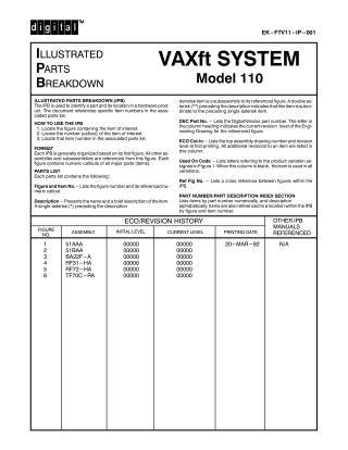
Digital PDFs
Documents
Guest
Register
Log In
EK-FVT11-IP-001
March 1992
22 pages
Original
0.6MB
view
download
OCR Version
4.5MB
view
download
Document:
VAXft System Model 100 IPB
Order Number:
EK-FVT11-IP
Revision:
001
Pages:
22
Original Filename:
OCR Text
digitall EK-FTV11-IP-001 ILLUSTRATED PARTS BREAKDOWN VAXft SYSTEM Model 110 ILLUSTRATED PARTS BREAKDOWN (IPB) denotes item is a subassembly to its referenced figure. A double as- The IPB is used to identify a part and its location in a hardware prod- terisk (**) preceding the description indicates that this item is subor- uct. The document references specific item numbers in the associated parts list. dinate to the preceding single asterisk item. DEC Part No. — Lists the Digital/Vendor part number. The letter in HOW TO USE THE IPB the column heading indicates the current revision level of the Engineering Drawing for the referenced figure. 1. Locate the figure containing the item of interest. 2. Locate the number (callout) of the item of interest. 3. Locate that item number in the associated parts list. ECO Cut-In — Lists the top assembly drawing number and revision FORMAT Each IPB is generally organized based on its first figure. All other assemblies and subassemblies are referenced from this figure. Each figure contains numeric callouts of all major parts (items). level at first printing. All additional revisions to an item are listed in this column. Used On Code — Lists letters referring to the product variation assigned in Figure 1. When this column is blank, the itemis usedin all variations. PARTS LIST Each parts list contains the following: Figure and Item No.— Lists the figure number and its referenced numeric callout Description — Presents the name and a brief description of the item. A single asterisk (*) preceding the description ——— NO. Ref Fig No. — Lists a cross reference between figures within the IPB. PART NUMBER/PART DESCRIPTION INDEX SECTION Lists items by part number numerically, and description alphabetically. ltems are also referenced to a location within the IPB by figure and item number. ECO/REVISION HISTORY ASSEMBLY INITIAL LEVEL CURRENT LEVEL PRINTING DATE 20-MAR-92 1 51AAA 00000 00000 3 BA22F—A 00000 00000 4 RF31—HA 00000 00000 5 RF72—HA 00000 00000 6 TF70C—RA 00000 00000 2 51BAA OTHER IPB 00000 00000 MANUALS REFERENCED N/A Digital Equipment Corporation reserves the right, without notice, to make substitutions and modifications in the specifications of products documented in this manual and further reserves the right to withdraw any of these products from the market without notice. Digital Equipment Corporation is not responsible for errors which may appear in the technical description (including illustrations and photographs) of the products covered by this manual. None of the descriptions contained in this manual imply the granting of any license whatsoever to make, use or sell equipment constructed in accordance therewith. Restricted Rights: Use, duplication or disclosure by the U.S. Government is subject to restrictions as set forth in subparagraph (c) (1) (ii) of the Rights in Technical Data and Computer Software clause at DFARS 252.227-2713. Copyright © 1992 by Digital Equipment Corporation. All rights reserved. Printed in U.S.A. The postage —paid READER’S COMMENTS form on the last page of this document requests your critical evaluation to assist us in preparing future documentation. The following are trademarks of Digital Equipment Corporation : DECdirect, VAXft and the DIGITAL logo. This manual was prepared and published by Documentation and Course Development, Digital Equipment Corporation. = <1 INDICATES FRU LEVEL PARTS. PARTS LIST} VFT11-01-IL Figure 1. Pedestal Assembly, VAXft Model 110 IPB-VFT11 FIG.& A ITEM NO. 1- 1 DESCRIPTION DEC ECO CUT-IN| USED | REF oN | FIG PART NO. | 31552 | cobEe | No. PEDESTAL ASSEMBLY, VAXft MODEL 110 51AAA-XE A PEDESTAL ASSEMBLY, VAXft MODEL 110 51AAA-XJ B *CABINET ASSEMBLY, POWER BA22F-AA A 3 *CABINET ASSEMBLY, POWER BA22F-AB B 3 2 | *Enclosure Assembly 70—-29782-01 3 | *Label, Pedestal VAXft 110 (120 V) 36—27838—-67 A *Label, Pedestal VAXft 110 (240 V) 36—-27838-68 B =4 | *Harness Assembly, ESD Wriststrap 5 | *DOOR ASSEMBLY, FRONT 6 *Medallion, “VAXft System Model 110” 12-24023-04 70-29784-01 74-43802-01 =7 | *Module, 5200 Filler Test T3999-AA =8 | *Module, 32 MB ECC Single Memory 1 MB DRAM |MS520-BA =9 *Module, 60 NS Fault Tolerant CPU KA510—-AA =10 *Module, Fault Tolerant Ethernet/DSSI Adaptor KFE52-AA =11 *Connector, D—Sub 25 Position 12-15336-08 =12 *Connector, Terminator 12-28976—-01 13 *Label, “Attention Pre—installed Software” 36—-28979-01 14 *Label, Power Cord 36—-27840-01 15 | *Cap Assembly, Base 70—-27905-02 16 *Base, Casting 74-44638-01 17 | *Nut, Kep 10—32 x 3/8 90-06565—-00 18 70-28960—-01 *Bracket Assembly, Wheel 18A | *Screw, Machine Pan Hd 1/4—-20 x 1/2 90-06056—01 18B | *Washer, Helical Split 90-07797-00 =19 | *PANEL, OCP (SEE NOTE) =19A | **Module, OCP =20 | *STORAGE ELEMENT, RF72 (2 GB, 5 1/4 INCH, 70-28967 —01 54-21059-01 RF72-HA FULL HEIGHT DSSI) (OPTIONAL) =21 *PANEL, OCP (SEE NOTE) =21A | **Module, OCP =22 | *STORAGE ELEMENT, RF31 (2 GB, 5 1/4 INCH, 70-28965-01 54-21059-01 RF31-HA HALF HEIGHT DSSI) (OPTIONAL) NOTE: OCP Panels, Items 19 and 21, must be removed to install Storage Elements, ltems 20 and 22, and must be replaced after installation. ITEMS (Not Shown) (Shipped Separately in Poly Bag w/System) *Cable, X—Link 50 Cond 17-02194-01 *Cord, Power 8 ft. 120V 17-00083-43 *Cable Assembly, Oval 6 Cond 17-00811-05 LABELS (Not Shown) *Label, EMI Postcard, German IPB-VFT11 36-35900-09 = <1 INDICATES FRU LEVEL PARTS. PARTS LIST} 12=1 131 SAEE8RANRSNERE°SRNE s < VFT11-02-IL Figure 2. Rackmount Assembly, VAXft Model 110 IPB-VFT11 FIG.& ITEM NO. 2— 1 2 DESCRIPTION DEC A 51BAA-XE A RACKMOUNT ASSEMBLY, VAXft MODEL 110 51BAA-XJ B *CABINET ASSEMBLY, POWER BA22F-AA A 3 *CABINET ASSEMBLY, POWER BA22F-AB B 3 36—-28979-01 *Module, Fault Tolerant Ethernet/DSSI Adaptor KFE52—-AA =4 *Module, 60 NS Fault Tolerant CPU KA510—-AA =5| *Module, 32 MB ECC Single Memory 1 MB DRAM | MS520—-BA =6| *Module, 5200 Filler Test T3999-AA =7| *Connector, D—Sub 25 Position 12-15336-08 =8 *Connector, Terminator 12-28976—-01 *Label, Power Cord 36—27840-01 *PANEL, OCP (SEE NOTE) 70—-28967 —01 **Module, OCP 54-21059-01 =11 * STORAGE ELEMENT, RF72 (2 GB, 5 1/4 INCH, RF72-HA 12| *Panel, OCP (See Note) 70—-28965—-01 **Module, OCP 54-21059-01 *STORAGE ELEMENT, RF31 (2 GB, 5 1/4 INCH, RF31-HA =10A| FULL HEIGHT DSSI) (OPTIONAL) =12A| =13| HALF HEIGHT DSSI) (OPTIONAL) NOTE: OCP Panels, Items 10 and 12, must be removed to install Storage Elements, ltems 11 and 13, and must be replaced after installation. ITEMS (Not Shown) (Shipped Separately in Poly Bag w/System) *Cable, X—Link 50 Cond 17-02194-01 *Cord, Power 8 ft. 120V 17-00083-43 *Cable Assembly, Oval 6 Cond 17-00811-02 *Harness Assembly, ESD Wriststrap 12-24023-04 LABELS (Not Shown) *Label, EMI Postcard, German IPB-VFT11 [coDE | NoO. RACKMOUNT ASSEMBLY, VAXft MODEL 110 *Label, “Attention Pre—installed Software” 9 CUT-IN UgfiD ':FGF PART NO. | 31302 =3| =10 ECO 36-35900-09 = <1 INDICATES FRU LEVEL PARTS. PARTS L|ST> * IF TWO RF31 DRIVES ARE INSTALLED, 5A<1 MOVE COUNTER WEIGHT TO POSITION 2. VFT11-03-IL Figure 3. Cabinet Assembly, Power (Sheet 1 of 4) -5- IPB-VFT11 = <1 INDICATES FRU LEVEL PARTS. PARTS LIST} VFT11-03A-IL Figure 3. Cabinet Assembly, Power (Sheet 2 of 4) IPB-VFT11 = <1 INDICATES FRU LEVEL PARTS. PARTS LIST} VFT11-03B-IL Figure 3. Cabinet Assembly, Power (Sheet 3 of 4) IPB-VFT11 = <1 INDICATES FRU LEVEL PARTS. PARTS LIST} = 30 = 31 = 28 = 31 > L- - - T @ O Figure 3. Cabinet Assembly, Power (Sheet 4 of 4) IPB-VFT11 | = FIG.& ITEM NO. 3- 1 2| =3| DEC DESCRIPTION a| PART NO. (BR22F A | cobE | No. CABINET ASSEMBLY, POWER (120V) BA22F-AA A 1,2 CABINET ASSEMBLY, POWER (240V) BA22F-AB B 1,2 *Frame Assembly 70—-28958-01 *Fan Tray Assembly (120V) 70—-28962—-01 *Fan Tray Assembly (240V) 70—-28962—-02 B *Power Supply Assembly (120V) H7868—-A A *Power Supply Assembly (240V) H7868—-B B =4| *Harness Assembly, Power Distribution 17-03200-01 =5 *PANEL ASSEMBLY, OCP (LEFT) 74—-28965—-01 =5A| *PANEL ASSEMBLY, OCP (RIGHT) 74—-28967—-01 =5B| **Module, OCP 54-17637-01 6] *Screw, Machine Phl Pan Hd No. 6—32 x 3/8 90-06022—-01 7] *Washer, Flat 90-06659—-00 =8| *Cable Assembly, OCP to RFXX Drives 17-01936—-01 9] *Module, TFK70 Controller 54-19085—-01 =10] ECO cut-in | “58° | Fig *Cable Assembly, OCP to Backplane 17-01964-01 11 *Bulkhead, Modem 74—-42946-01 12| *Screw, Machine Phl Pan Hd No. 6-32 x 1/4 90-06020—-01 13| *Finger, Grounding 12-26922-01 =14 *Adaptor, 25 Pin with EOS H8575—-A 15| *Cable Assembly, Bulkhead to Console Prot. 17-03297-01 =16 *Module, Console Protection 54-19491-01 =17 *DRIVE KIT ASSEMBLY, TF70C TF70C—-RA =18 *Harness Assembly, Console Prot. Panel to 17-03296-01 A 6 Backplane 19| *Plate, Modem (Center) 74-42948-01 20| *Label, Pedestal (120V) 36—27838—-67 A *Label, Pedestal (240V) 36—27838—-68 B *Plate, Modem (Right) 74-42946-01 21 22| *Cable Assembly, Drive Control Module to Drive | 17—-03199-01 23| *Cable Assembly, Tape Extension DSSI 17-03334-01 24| *Cable Assembly, DSSI 17-03333-01 =25 *Connector, Terminator 12-28976—-01 =26 *Module, DC to DC Converter 54-20074-01 27| *Cable Assembly, DC to DC Module to Backplane| 17-03296-01 28| * STORAGE ELEMENT, RF72 (2 GB, 5 1/4 INCH, RF72—-HA FULL HEIGHT DSSI) (OPTIONAL) =29 *STORAGE ELEMENT, RF31 (2 GB, 5 1/4 INCH, RF31-HA HALF HEIGHT DSSI) (OPTIONAL) =30 *Bracket, Dual RF31 or Single RF72 Shockmount | 70—-28969—-01 =31 *Bracket, Dual RF31 or Single RF72 74—-42954-01 -9 - IPB—VFT11 FIG.& ITEM NO. DEC DESCRIPTION A 32| *Screw, Machine Flat Hd No. 6—32 x 5/32 90-00039-28 33| *Nut, Hex Hd No. 6—-32 90-06558—-00 *Counter Weight, RF31 (See Note) 74-43838—-01 *Screw, Machine Flat Hd No. 6—32 x 3/8 90-06022—-02 35| 36| *Bracket, Dual RF31 or Single RF72 Shockmount | 70—-28969—-02 37 *Fingerstock 12-26200—-02 38 *Cover, Rear 74-42945-01 39| *Module, Backplane 54-20251-01 40 *Screw, Machine Phl Pan Hd No. 10—32 x 1 Inch 90-06022-02 41 *Bracket, TF70C Tape Drive 70—-28959-01 NOTE: Item 34, Counter Weight to be used only if two item 29, RF31 Storage Elements are installed. ITEMS (Not Shown) IPB-VFT11 CUT-IN UgfiD FiG PART NO. [BA22F A | cobEe | No. 3_ 34| ECO *Clamp, Cable 90-09636—-00 *Clip, Cable 12-21249-01 *Grommet 12-25469-01 *Screw, Machine Phl Pan Hd No. 4—-40 x 5/32 90-08032—-01 - 10 - PARTS LIST} = <1 INDICATES FRU LEVEL PARTS. iy rns y e00 I- o) ¢0 o // < 0 VFT11-04-IL Figure 4. Drive Kit Assembly, TF70C - 11 - IPB-VFT11 FIG.& ITEM NO. 4- DEC DESCRIPTION 2| 2A| ECO CUT-IN| ysep | REF ‘oN | FIG PART NO. | TF70C | copE | No. DRIVE KIT ASSEMBLY, TF70C =1 Al TF70C-RA *Drive, TK70 w/o Skid Plate and Cartridge 1,2,3 TK70—-EA *PANEL ASSEMBLY, OCP TAPE (RIGHT) 70—-28966—01 **Module, OCP 54-17637-01 3| “*Insulator Assembly 70—-21765-01 4| *Screw, Machine Phl Pan Hd No. 6—-32 x 3/8 74-40399-01 5 *Washer, Lock 90-09882-00 Q IPB—VFT11 -12 - PART NUMBER/DESCRIPTION INDEX } INDEX BY DEC PART NUMBER VAXft SYSTEM Model 110 PART NO. DESCRIPTION FIG NO. ITEM NO. 12-15336-08 12-15336-08 12-21249-01 12-24023-04 12-24023-04 Connector, D—Sub 25 Position Connector, D—Sub 25 Position Clip, Cable Harness Assembly, ESD Wriststrap Harness Assembly, ESD Wriststrap 1 2 3 1 2 11 7 Not Shown 4 Not Shown 12-25469-01 Grommet 3 Not Shown 12-26200-02 Fingerstock 3 37 12-26922-01 Finger, Grounding 3 13 12-28976—-01 12-28976—-01 12-28976—-01 Connector, Terminator Connector, Terminator Connector, Terminator 3 1 2 25 12 8 17-00083-43 17-00083-43 17-00811-02 17-00811-05 17-01936-01 17-01964-01 17-02194-01 Cord, Power 8 ft. 120V Cord, Power 8 ft. 120V Cable Assembly, Oval 6 Cond Cable Assembly, Oval 6 Cond Cable Assembly, OCP to RFXX Drives Cable Assembly, OCP to Backplane Cable, X—Link 50 Cond 1 2 2 1 3 3 1 Not Shown Not Shown Not Shown Not Shown 8 10 Not Shown 17-02194-01 Cable, X—Link 50 Cond 2 17-03199-01 17-03200-01 Cable Assembly, Drive Control Module to Drive Harness Assembly, Power Distribution 3 3 Not Shown 22 4 17-03296—-01 17-03296—-01 Harness Assembly, Console Prot. Panel to Backplane Cable Assembly, DC to DC Module to Backplane 3 3 18 27 17-03297-01 17-03333-01 17-03334-01 Cable Assembly, Bulkhead to Console Prot. Cable Assembly, DSSI Cable Assembly, Tape Extension DSSI 3 3 3 15 24 23 36—27838—-67 36—27838—-67 36—-27838—-68 36—-27838—-68 Label, Pedestal VAXft 110 (120 V) Label, Pedestal (120V) Label, Pedestal VAXft 110 (240 V) Label, Pedestal (240V) 1 3 1 3 3 20 3 20 36—27840-01 36—27840-01 36—28979-01 36—28979-01 Label, Power Cord Label, Power Cord Label, “Attention Pre—installed Software” Label, “Attention Pre—installed Software” 1 2 1 2 14 9 13 2 36—35900—-09 36—35900—-09 Label, EMI Postcard, German Label, EMI Postcard, German 1 2 Not Shown Not Shown 51AAA-XE 51AAA-XJ PEDESTAL ASSEMBLY, VAXft MODEL 110 PEDESTAL ASSEMBLY, VAXft MODEL 110 1 1 N/A N/A 51BAA-XE 51BAA-XJ RACKMOUNT ASSEMBLY, VAXft MODEL 110 RACKMOUNT ASSEMBLY, VAXft MODEL 110 2 2 N/A N/A 54-17637-01 54-17637-01 54-19085-01 54-19491-01 54-20074-01 54-20251-01 54-21059-01 54-21059-01 54-21059-01 54-21059-01 Module, OCP Module, OCP Module, TFK70 Controller Module, Console Protection Module, DC to DC Converter Module, Backplane Module, OCP Module, OCP Module, OCP Module, OCP 4 3 3 3 3 3 1 2 1 2 2A 5B 9 16 26 39 21A 10A 19A 12A 1 A-1 IPB-VFT11 INDEX BY DEC PART NUMBER VAXit SYSTEM Model 110 DESCRIPTION FIG NO. ITEM NO. 70—-21765-01 Insulator Assembly 4 3 70—-27905-02 70—-28958—-01 Cap Assembly, Base Frame Assembly 1 3 15 1 70-28959-01 Bracket, TF70C Tape Drive 3 41 70-28960—-01 70—-28962—-01 70—28962—-02 70—-28965—-01 Bracket Assembly, Wheel Fan Tray Assembly (120V) Fan Tray Assembly (240V) Panel, OCP 1 3 3 1 18 2 2 21 70—-28965—-01 70—-28966—01 70—-28967—01 70—-28967—01 70—-28969—-01 70—-28969—-02 70—-29782-01 70—-29784—-01 Panel, OCP Panel Assembly, OCP Tape (Right) Panel, OCP Panel, OCP Bracket, Dual RF31 or Single RF72 Shockmount Bracket, Dual RF31 or Single RF72 Shockmount Enclosure Assembly DOOR ASSEMBLY, FRONT 2 4 2 1 3 3 1 1 12 2 10 19 30 36 2 5 74—-28965—-01 74—-28967—-01 Panel Assembly, OCP (Left) Panel Assembly, OCP (Right) 3 3 5 5A 74-40399-01 74-42945-01 74—-42946-01 74-42946-01 Screw, Machine Phl Pan Hd No. 6—-32 x 3/8 Cover, Rear Bulkhead, Modem Plate, Modem (Right) 4 3 3 3 4 38 11 21 74—-42948-01 74—-42954-01 Plate, Modem (Center) Bracket, Dual RF31 or Single RF72 3 3 19 31 74-43802-01 74-43838-01 Medallion, “VAXft System Model 110” Counter Weight, RF31 1 3 6 34 74-44638-01 Base, Casting 1 16 90-00039—-28 90-06020—-01 Screw, Machine Flat Hd No. 6—-32 x 5/32 Screw, Machine Phl Pan Hd No. 6—-32 x 1/4 3 3 32 12 90-06022-01 Screw, Machine Phl Pan Hd No. 6—-32 x 3/8 3 6 90-06022—-02 Screw, Machine Phl Pan Hd No. 10—-32 x 1 Inch 3 40 90-06022-02 Screw, Machine Flat Hd No. 6—-32 x 3/8 3 35 90-06056—-01 90-06558—-00 Screw, Machine Pan Hd 1/4—-20 x 1/2 Nut, Hex Hd No. 6—-32 1 3 18A 33 90-06565—00 90-06659-00 90-07797-00 Nut, Kep 10—-32 x 3/8 Washer, Flat Washer, Helical Split 1 3 1 17 7 18B 90-08032—-01 Screw, Machine Phl Pan Hd No. 4—-40 x 5/32 3 Not Shown 90-09636—00 90-09882-00 Clamp, Cable Washer, Lock 3 4 Not Shown 5 BA22F-AA BA22F-AA BA22F-AA CABINET ASSEMBLY, POWER CABINET ASSEMBLY, POWER (120V) CABINET ASSEMBLY, POWER 1 3 2 1 N/A 1 BA22F-AB BA22F-AB BA22F-AB CABINET ASSEMBLY, POWER (240V) CABINET ASSEMBLY, POWER CABINET ASSEMBLY, POWER 3 1 2 N/A 1 1 H7868—-A Power Supply Assembly (120V) 3 3 H7868—-B Power Supply Assembly (240V) 3 3 H8575—-A Adaptor, 25 Pin with EOS 3 14 KA510—-AA KA510—-AA Module, 60 NS Fault Tolerant CPU Module, 60 NS Fault Tolerant CPU 2 1 4 9 PART NO. IPB-VFT11 INDEX BY DEC PART NUMBER VAXft SYSTEM Model 110 PART NO. DESCRIPTION FIG NO. ITEM NO. KFE52—-AA KFE52—-AA Module, Fault Tolerant Ethernet/DSSI Adaptor Module, Fault Tolerant Ethernet/DSSI Adaptor 1 2 10 3 MS520—-BA MS520—-BA Module, 32 MB ECC Single Memory 1 MB DRAM Module, 32 MB ECC Single Memory 1 MB DRAM 2 1 5 8 RF31-HA STORAGE ELEMENT, RF31 (2 GB, 5 1/4 INCH, HALF HEIGHT DSSI) (OPTIONAL) 1 22 RF31-HA STORAGE ELEMENT, RF31 (2 GB, 5 1/4 INCH, HALF HEIGHT DSSI) (OPTIONAL) STORAGE ELEMENT, RF31 (2 GB, 5 1/4 INCH, HALF HEIGHT DSSI) (OPTIONAL) 3 29 2 13 1 20 2 11 3 28 RF31-HA RF72—-HA STORAGE ELEMENT, RF72 (2 GB, 5 1/4 INCH, FULL HEIGHT DSSI) (OPTIONAL) RF72—-HA STORAGE ELEMENT, RF72 (2 GB, 5 1/4 INCH, FULL HEIGHT DSSI) (OPTIONAL) RF72—-HA STORAGE ELEMENT, RF72 (2 GB, 5 1/4 INCH, FULL HEIGHT DSSI) (OPTIONAL) T3999—-AA T3999—-AA Module, 5200 Filler Test Module, 5200 Filler Test 2 1 6 7 TF70C—-RA TF70C—-RA TK70—-EA DRIVE KIT ASSEMBLY, TF70C DRIVE KIT ASSEMBLY, TF70C Drive, TK70 w/o Skid Plate and Cartridge 4 3 4 N/A 17 1 1 A-3 IPB-VFT11 INDEX BY DEC PART DESCRIPTION DESCRIPTION VAXit SYSTEM Model 110 DEC PART NO. FIG. NO. ITEM NO. Adaptor, 25 Pin with EOS H8575—-A 3 14 Base, Casting Bracket Assembly, Wheel Bracket, Dual RF31 or Single RF72 Bracket, Dual RF31 or Single RF72 Shockmount Bracket, Dual RF31 or Single RF72 Shockmount Bracket, TF70C Tape Drive 74-44638-01 70—-28960-01 74—-42954-01 70—-28969—-02 70—-28969—-01 70-28959-01 1 1 3 3 3 3 16 18 31 36 30 41 Bulkhead, Modem 74-42946-01 3 11 CABINET ASSEMBLY, POWER CABINET ASSEMBLY, POWER BA22F-AA BA22F-AA 1 2 1 1 CABINET ASSEMBLY, POWER CABINET ASSEMBLY, POWER BA22F-AB BA22F-AB 2 1 1 1 CABINET ASSEMBLY, POWER (120V) BA22F-AA 3 N/A CABINET ASSEMBLY, POWER (240V) BA22F-AB 3 N/A Cable Assembly, Bulkhead to Console Prot. 17-03297-01 3 15 Cable Assembly, DC to DC Module to Backplane 17-03296—-01 3 27 Cable Assembly, Drive Control Module to Drive Cable Assembly, DSSI 17-03199-01 17-03333-01 3 3 22 24 Cable Assembly, OCP to Backplane Cable Assembly, OCP to RFXX Drives Cable Assembly, Oval 6 Cond Cable Assembly, Oval 6 Cond Cable Assembly, Tape Extension DSSI Cable, X—Link 50 Cond Cable, X—Link 50 Cond 17-01964-01 17-01936-01 17-00811-05 17-00811-02 17-03334-01 17-02194-01 17-02194-01 3 3 1 2 3 1 2 10 8 Not Shown Not Shown 23 Not Shown Not Shown Cap Assembly, Base Clamp, Cable 70—-27905-02 90-09636—-00 1 3 15 Not Shown Clip, Cable 12-21249-01 3 Not Shown Connector, D—Sub 25 Position Connector, D—Sub 25 Position Connector, Terminator Connector, Terminator Connector, Terminator Cord, Power 8 ft. 120V Cord, Power 8 ft. 120V Counter Weight, RF31 Cover, Rear 12-15336-08 12-15336-08 12-28976-01 12-28976-01 12-28976-01 17-00083-43 17-00083-43 74-43838-01 74-42945-01 2 1 3 1 2 1 2 3 3 7 11 25 12 8 Not Shown Not Shown 34 38 DOOR ASSEMBLY, FRONT DRIVE KIT ASSEMBLY, TF70C DRIVE KIT ASSEMBLY, TF70C Drive, TK70 w/o Skid Plate and Cartridge 70—-29784-01 TF70C—-RA TF70C—-RA TK70—-EA 1 3 4 4 5 17 N/A 1 Enclosure Assembly 70—-29782-01 1 2 Fan Tray Assembly (120V) 70-28962—-01 3 2 Fan Tray Assembly (240V) 70-28962-02 3 2 Finger, Grounding 12-26922-01 3 13 Fingerstock 12-26200-02 3 37 Frame Assembly 70—-28958—-01 3 1 Grommet 12-25469-01 3 Not Shown Harness Assembly, Console Prot. Panelt o Backplane Harness Assembly, ESD Wriststrap 17-03296-01 12-24023-04 3 1 18 4 B-1 IPB-VFT11 INDEX BY DEC PART DESCRIPTION VAXit SYSTEM Model 110 DESCRIPTION DEC PART NO. FIG. NO. ITEM NO. Harness Assembly, ESD Wriststrap Harness Assembly, Power Distribution 12-24023-04 17-03200-01 2 3 Not Shown 4 Insulator Assembly 70—-21765-01 4 3 Label, “Attention Pre—installed Software” Label, “Attention Pre—installed Software” Label, EMI Postcard, German Label, EMI Postcard, German Label, Pedestal (120V) Label, Pedestal (240V) Label, Pedestal VAXft 110 (120 V) Label, Pedestal VAXft 110 (240 V) Label, Power Cord Label, Power Cord 36—-28979-01 36—-28979-01 36—35900-09 36—35900-09 36—27838—-67 36—27838—-68 36—-27838—-67 36—-27838-68 36—27840-01 36—27840-01 1 2 2 1 3 3 1 1 1 2 13 2 Not Shown Not Shown 20 20 3 3 14 9 Medallion, “VAXft System Model 110” Module, 32 MB ECC Single Memory 1 MB DRAM Module, 32 MB ECC Single Memory 1 MB DRAM 74-43802-01 MS520-BA MS520-BA 1 1 2 6 8 5 Module, 5200 Filler Test Module, 5200 Filler Test T3999—-AA T3999—-AA 2 1 6 7 Module, 60 NS Fault Tolerant CPU Module, 60 NS Fault Tolerant CPU Module, Backplane Module, Console Protection Module, DC to DC Converter KA510—-AA KA510—-AA 54-20251-01 54-19491-01 54-20074-01 1 2 3 3 3 9 4 39 16 26 Module, Fault Tolerant Ethernet/DSSI Adaptor Module, Fault Tolerant Ethernet/DSSI Adaptor KFE52-AA KFE52—-AA 2 1 3 10 Module, OCP Module, OCP Module, OCP Module, OCP Module, OCP Module, OCP Module, TFK70 Controller 54-17637-01 54-21059-01 54-17637-01 54-21059-01 54-21059-01 54-21059-01 54-19085-01 4 1 3 2 2 1 3 2A 21A 5B 12A 10A 19A 9 Nut, Hex Hd No. 6—-32 90-06558-00 3 33 Nut, Kep 10—32 x 3/8 90-06565—-00 1 17 Panel Assembly, OCP (Left) 74-28965-01 3 5 Panel Assembly, OCP (Right) Panel Assembly, OCP Tape (Right) Panel, OCP Panel, OCP Panel, OCP Panel, OCP PEDESTAL ASSEMBLY, VAXft MODEL 110 PEDESTAL ASSEMBLY, VAXft MODEL 110 74—-28967—01 70—-28966—01 70-28967 —01 70-28965-01 70-28967 —01 70-28965-012 51AAA-XE 51AAA-XJ 3 4 2 1 1 2 1 1 5A 2 10 21 19 12 N/A N/A Plate, Modem (Center) 74-42948-01 3 19 Plate, Modem (Right) 74-42946-01 3 21 Power Supply Assembly (120V) H7868—-A 3 3 Power Supply Assembly (240V) H7868—-B 3 3 RACKMOUNT ASSEMBLY, VAXft MODEL 110 RACKMOUNT ASSEMBLY, VAXft MODEL 110 51BAA-XE 51BAA-XJ 2 2 N/A N/A Screw, Machine Flat Hd No. 6—-32 x 3/8 Screw, Machine Flat Hd No. 6-32 x 5/32 90-06022-02 90-00039-28 3 3 35 32 IPB-VFT11 B-2 INDEX BY DEC PART DESCRIPTION DESCRIPTION VAXit SYSTEM Model 110 DEC PART NO. FIG. NO. ITEM NO. Screw, Machine Pan Hd 1/4-20 x 1/2 90-06056—-01 1 18A Screw, Machine Phl Pan Hd No. 10—-32 x 1 Inch Screw, Machine Phl Pan Hd No. 4—40 x 5/32 Screw, Machine Phl Pan Hd No. 6—-32 x 1/4 Screw, Machine Phl Pan Hd No. 6—32 x 3/8 Screw, Machine Phl Pan Hd No. 6—32 x 3/8 90-06022-02 90-08032-01 90-06020-01 90-06022-01 74—-40399-01 3 3 3 3 4 40 Not Shown 12 6 4 STORAGE ELEMENT, RF31 (2 GB, 5 1/4 INCH, HALF HEIGHT DSSI) (OPTIONAL) STORAGE ELEMENT, RF31 (2 GB, 5 1/4 INCH, HALF HEIGHT DSSI) (OPTIONAL) STORAGE ELEMENT, RF31 (2 GB, 5 1/4 INCH, HALF HEIGHT DSSI) (OPTIONAL) RF31-HA 2 13 RF31-HA 3 29 RF31-HA 1 22 STORAGE ELEMENT, RF72 (2 GB, 5 1/4 INCH, RF72—-HA 2 11 RF72—-HA 3 28 RF72—-HA 1 20 Washer, Flat 90-06659—-00 3 7 Washer, Helical Split Washer, Lock 90-07797-00 90-09882-00 1 4 5 FULL HEIGHT DSSI) (OPTIONAL) STORAGE ELEMENT, RF72 (2 GB, 5 1/4 INCH, FULL HEIGHT DSSI) (OPTIONAL) STORAGE ELEMENT, RF72 (2 GB, 5 1/4 INCH, FULL HEIGHT DSSI) (OPTIONAL) B-3 18B IPB-VFT11 READER’S COMMENTS VAXft SYSTEM Model 110 lllustrated Parts Breakdown EK-FTV1i1-I1P-001 . How did you use this manual? (Circle your response.) (a) Installation (c) Maintenance (e) Training (b) Operation/Use (d) Programming (f) Other (Please specify) 2. Did the manual meet your needs? Yes [ No [] Why? 3. Please rate the manual on the following categories. (Circle your response.) Excellent Good Fair Poor Unacceptable Accuracy 5 4 3 2 1 Clarity Completeness 5 5 4 4 3 3 2 2 1 1 lllustrations, examples 5 4 3 2 1 Overall ease of use Table of Content, Index 5 5 4 4 3 3 2 2 1 1 4. What things did you like most about this manual? 5. What things did you like least about this manual? 1] «Q 11/] U 6. Please list and describe any errors you found in the manual. Description/Location of Error 7. Which of the following most clearly describes your job ? (Circle your response.) (@) Administrative Support (e) System Manager (i) Education/Trainer (b) Manager/Supervisor (c) Scientist/Engineer (d) Programmer/Analyst (f) Computer Operator (g) Software Support (h) Hardware Support (j) Sales/Marketing (k) Other (Please specify) OPTIONAL INFORMATION Name Job Title Street Company City Department State/Country Telephone Number Postal (ZIP) Code Date THANK YOU FOR YOUR COMMENTS AND SUGGESTIONS. Please do not use this form to order manuals. Contact your representative at Digital Equipment Corporation or (in the USA) call our DECdirectTM department at this toll—free number : 800—344—-4825 © 1992 by Digital Equipment Corporation. All Rights Reserved. MYO
Home
Privacy and Data
Site structure and layout ©2025 Majenko Technologies