BDV11 Bus Terminator, Bootstrap, and Diagnostic ROM Technical Manual
Order Number: EK-BDV11-TM
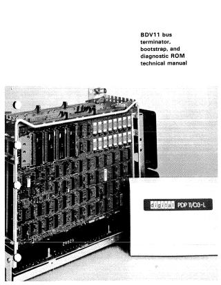
This document is the "BDV11 bus terminator, bootstrap, and diagnostic ROM technical manual," published by Digital Equipment Corporation in March 1978, for use with the PDP 11/03-L and other LSI-11 bus systems.
The BDV11 is a quad-height printed circuit board (M8012 module) that serves multiple functions on an LSI-11 bus:
- Bus Termination: Provides 120-ohm terminations for LSI-11 bus signal lines.
- ROM Hosting: Includes fixed 4K words of diagnostic and bootstrap ROM, plus user-available space for 2K words of erasable, programmable ROM (EPROM) and 16K words of ROM/EPROM. All ROM is mapped into a 256-word segment of the LSI-11 I/O address space (173000–173776) via a Page Control Register (PCR), which allows various "pages" (128-word blocks) of ROM to be accessed. Jumper settings on the module determine the specific ROM socket assignments and influence boot sequences.
- Diagnostic Aids: Features switches (HALT/ENABLE, RESTART, and diagnostic/bootstrap program selection) and a diagnostic light display (LEDs) to monitor system status and indicate failures.
The manual provides comprehensive details on:
- Installation: Steps for inserting the module into an LSI-11 quad backplane, including pre-installation switch settings and bus pin-outs.
- Operation: Functions of all switches and indicators, and descriptions of the six hardware registers (Page Control, Read/Write, Switch, Display, and BEVNT) used for system control and maintenance.
- Technical Description: In-depth explanations of the BDV11's internal logic, including its bus transceivers, control logic, ROM address and socket selection mechanisms, power-up logic, BEVNT (line-time clock) logic, and display logic.
- Specifications: Physical, electrical, and environmental specifications for the BDV11 module, along with recommended ROM specifications.
The document is intended for technical users familiar with the LSI-11 microcomputer, detailing the module's design, functionality, and interaction within an LSI-11 bus system.

Site structure and layout ©2025 Majenko Technologies