W707
Order Number: XX-90073-5A
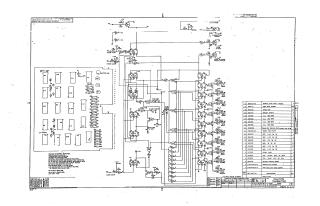
This document is a schematic diagram for a Teletype Transmitter module, identified as Part No. CS W707-0-1, designed by Digital Equipment Corporation (DEC) and copyrighted in 1968.
The schematic details the electronic circuit responsible for converting parallel digital input bits (Bits 1 through 8) into serial data suitable for driving a Teletype printing device. Key functional blocks include:
- Input sections for parallel data, clock, clear, and power.
- Logic gates and flip-flops for data serialization and control (e.g., "Clear Flag," "Power Clear").
- Outputs for "Flag Strobe," "Flag Output," "Strobed Flag Output," and a "Print Selector Magnet Driver," indicating control over the Teletype's operation.
- A "Word Length Jumper" suggests configurable data word size.
The circuit primarily utilizes specific Digital Equipment Corporation (DEC) integrated circuits, including:
- DEC889P Hex Inverters
- DEC882P Quad Input Gates
- DEC890P Quad 2-Input Power Buffers
- DEC853A Dual JK Flip-Flops It also incorporates DEC6534B transistors, various resistors (1/4W 5%), capacitors, and diodes, operating on a +3.6V supply.
The document states its purpose is for "TEST AND MAINTENANCE PURPOSES." A comprehensive parts list details all components used in the module.
Site structure and layout ©2025 Majenko Technologies