W607
Order Number: XX-A63A7-79
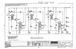
This document is a proprietary schematic diagram for a W607 Pulse Amplifier, developed by Digital Equipment Corporation and copyrighted in 1964.
Key information presented:
- Purpose: The schematic is furnished solely for test and maintenance purposes.
- Circuit Design: It depicts a multi-stage pulse amplifier, likely with three distinct amplification sections (indicated by similar groupings of transistors Q1/Q2, Q3/Q4, Q5/Q6, and transformers T1/T2, T3/T4, T5/T6).
- Components: The circuit extensively uses transistors (DEC2894-1B, DEC-6B), various diodes (D-662, D-664), transformers (T-2003, T-2046), resistors, and capacitors.
Specifications:
- Unless otherwise indicated, resistors are 1/4W, 10% tolerance.
- Capacitors are specified in MMFD (micromicrofarads, or picofarads), though some values like C1, C2, C3 are "220" which would typically be microfarads.
- Diodes are generally D-664.
Connectivity: It shows input points (D/E, K/L, R/S) and output points (F/H, M/N, T/U) for each stage, along with power connections (OC GND and OB-15V).
- Conversion Chart: A "Transistor & Diode Conversion Chart" provides equivalent EIA part numbers for the DEC components (e.g., D-662 converts to IN645, D-664 converts to IN3606).
- Administrative Details: The document includes a revision history (up to Revision H), a reference to a parts list (A-PL-W607-0-0), and the names and dates (July 29, 1964) of the designer (A. Ouellette), checker (N. Perryman), and engineer (R. Bank).
Site structure and layout ©2025 Majenko Technologies