W507
Order Number: XX-186F7-20
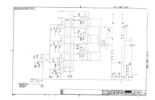
This document is a proprietary schematic diagram for the Digital Equipment Corporation's W507 Low Voltage Detector, copyrighted in 1970. It is intended for test and maintenance purposes only.
Key features and components:
- Function: It is designed as a "Low Voltage Detector."
- Core Circuitry: The circuit heavily utilizes multiple operational amplifiers (primarily UA710 and UA741C types, labeled E1-E8) to monitor various input lines with different voltage levels (e.g., -6.2"A", -6.2"B", +10V, +5V, -15V).
- Logic Gate: The outputs of these operational amplifiers feed into an 8-input logic gate (labeled E9, type DEC74H30), which likely combines the detection signals from the individual voltage monitoring stages.
- Output Stage: The output features transistors (2N4258, Q1 and Q2) and a series of diodes (D4-D7, D11-D15, D17-D18), suggesting it drives an indicator, alarm, or control signal based on the detected voltage conditions.
- Power Supplies: The circuit operates with multiple voltage rails, including +10V, +5V, and -15V.
- Standard Components: Unless otherwise indicated, resistors are 1/4W, 5% tolerance; capacitors are 0.01µF, 100V, 20%; and diodes are D662 (IN645).
- Component Conversion Chart: A table provides conversions between DEC part numbers (e.g., D664, D670, IN823, 2N4258, IN753A) and their EIA equivalents.
Site structure and layout ©2025 Majenko Technologies