W504
Order Number: XX-32DAC-86
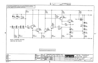
This document is a schematic diagram for the W504 Initial Transient Detector, copyrighted in 1966 by Digital Equipment Corporation.
Key information presented:
- Circuit Description: It details the electronic components and their interconnections for the W504, including transistors (Q1-Q6), diodes (D1-D13), resistors (R1-R15), and capacitors (C1-C3). It shows connections to power rails (+10V, GND, -15V) and various input/output points (SO, PO, F, JO).
- Proprietary Information: The schematic is for test and maintenance purposes only, and the circuits are proprietary to Digital Equipment Corporation.
- Component Specifications: A note indicates that, unless otherwise specified, resistors are 1/4W with 5% tolerance.
- Component Cross-Reference: A "Transistor & Diode Conversion Chart" provides cross-references for DEC part numbers (e.g., DEC 2894-3, D662) to their standard EIA equivalents (e.g., NONE, 1N645).
- Revision and Approval: The document includes sections for drawing, checking, engineering, and production dates (circa May 1966), and a revision history block.
Site structure and layout ©2025 Majenko Technologies