S603
Order Number: XX-9B128-B6
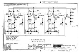
This document is a schematic diagram for the "PULSE AMPLIFIER S603" designed by Digital Equipment Corporation, copyrighted in 1965.
Key information includes:
- Purpose: The schematic is provided for test and maintenance purposes, and the circuits are proprietary.
- Circuit Description: It details the electronic components and connections for a pulse amplifier, featuring six transistors (Q1-Q6, primarily DEC 2894-2B type), numerous diodes (e.g., D-662, D-664), resistors, and capacitors. It shows connections for power supplies such as +10V(A) and -15V.
Component Specifications:
- Resistors are generally 1/4W, with most indicated as 5% tolerance, otherwise 10%.
- Capacitors are specified in micromicrofarads (MMFD).
- Default diodes are D-664 and transistors are DEC 3639-C, unless otherwise indicated.
Conversion Chart: A "Transistor & Diode Conversion Chart" provides EIA equivalents for DEC's internal part numbers, such as DEC 3639C corresponding to 2N3639, D662 to IN645, and D664 to IN3606.
- Manufacturing Note: It indicates to "USE THE ETCH BOARD OF THE R603."
- Revisions & Dates: The drawing was created by I. Hahn on 6-14-65, checked by R. Silverman, and engineered by R. Sogge on 6-18-65. The document is at Revision E, with a Printed Circuit Revision D.
Site structure and layout ©2025 Majenko Technologies