S107
Order Number: XX-2641D-22
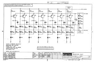
This document is a proprietary schematic diagram for a Digital Equipment Corporation (DEC) 'INVERTER S107' circuit, copyrighted in 1965. It is provided solely for test and maintenance purposes.
The circuit features multiple, similar transistor-diode inverter stages (Q1-Q7), indicating it's likely a multi-channel or multi-stage logic inverter.
Key details provided include:
- Standard Component Specifications: Resistors are specified as 1/4W, 5%; diodes are generally D-664; and transistors are DEC 3639B.
- Component Conversion Chart: A useful table cross-references DEC part numbers to their industry-standard EIA equivalents (e.g., DEC 3639B to 2N3639, D662 to 1N645, D664 to 1N3606).
- Power Rails: The circuit operates with +10V (A), -15V (B), Ground (C), and a -3V 'strate' (likely substrate or auxiliary) voltage.
- Associated Information: The document notes the printed circuit board revision (SIA for DGL board), refers to a parts list (A-PL-S107-0-0), and instructs to "USE THE ETCH BOARD OF THE R107".
- Revision History: The schematic itself is at Revision E, indicating several updates over time.
Site structure and layout ©2025 Majenko Technologies