R205
Order Number: XX-144A4-C0
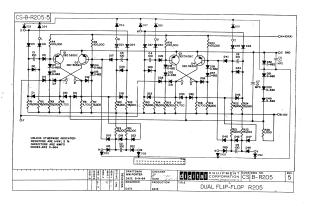
This document is an electrical schematic diagram titled "DUAL FLIP-FLOP R205," created by Digital Equipment Corporation on September 9, 1964, as Revision 5 of drawing CS-B-R205.
The schematic illustrates a circuit featuring two distinct flip-flop stages, each built around a pair of DEC 3639C transistors (Q1/Q2 and Q3/Q4). The circuit incorporates numerous passive components, including resistors (R1-R25) with values ranging from 1,500 to 100,000 ohms, and capacitors (C1-C8) with values of 100 (MMFD) or .01 MFD. A large number of diodes (D1-D62) are also used throughout the circuit for various functions.
Power supply connections indicate operation with +10V(A), Ground (GND), and -15V. General specifications provided note that resistors are 1/4W, 5% tolerance; capacitors are typically in micromicrofarads (MMFD) unless explicitly stated as microfarads (MFD); and diodes are of type D-664.
Site structure and layout ©2025 Majenko Technologies