M957
Order Number: XX-E8938-00
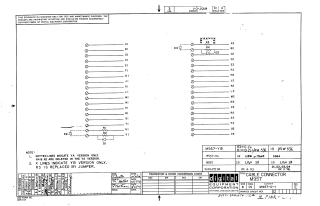
This document is a proprietary schematic diagram for a CABLE CONNECTOR M957 (part number M957-0-1, Revision E), copyrighted in 1970 by Digital Equipment Corporation. It is intended solely for test and maintenance.
The schematic illustrates interconnections between two sets of terminals (labeled AI-VI and A2-V2), utilizing various resistors (R1, R2, R3, R4) and diodes (D1, D2, D3, D4).
Key variations are specified:
- M957-YA Version: Resistors R4 and R2 (indicated by dotted lines) are deleted. R1 is specified as 1K Ohm 1/8W 1%MF.
- M957-YB Version: Resistor R3 (indicated by 'X' lines) is replaced by a jumper (R3=0 Ohm). R1 is 10 Ohm 1/4W 5%.
The document includes a revision history from A to E, with the latest revision dated December 8, 1972, and original drawing/checking dates from October-November 1970.
Site structure and layout ©2025 Majenko Technologies