M627
Order Number: XX-2F293-1D
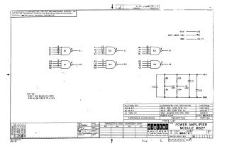
This document is a schematic diagram for the POWER AMPLIFIER MODULE M627 (Part Number M627-0-1, Revision F), created by Digital Equipment Corporation and copyrighted in 1967. It is provided for test and maintenance purposes, and the circuits are proprietary.
The schematic illustrates:
- Digital Logic: It incorporates several DEC74H40 Integrated Circuits (E1, E2, E3), each containing multiple 4-input logic gates with specified input and output pins. All ICs require Pin 7 connected to Ground and Pin 14 to +5V.
- Analog/Power Section: This section includes a network of resistors (R1 & R4 are 750 Ohm; R2 & R3 are 330 Ohm) and capacitors (C1, C2, C3 are .01 MFD), configured to provide +3V intermediate voltage points (UI, VI) and connect to the main +5V and Ground rails.
- Power Connections: The module utilizes a +5V supply (connected to A2) and Ground (C2, T1), with a -15V supply noted as "NOT USED" (B2).
A Parts List details the specific components: DEC74H40 integrated circuits, 330 Ohm and 750 Ohm resistors, and .01 MFD capacitors. The document includes design and approval dates from July 1967 and a revision history.
Site structure and layout ©2025 Majenko Technologies