M260
Order Number: XX-96976-F3
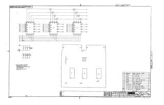
This document is a schematic diagram for a 16 Word x 12 Bit Associative Memory Cell, designated M260, created by Digital Equipment Corporation in 1971.
Key details from the document include:
- Purpose: Furnished for test and maintenance, noted as proprietary information.
- Main Components: The circuit primarily utilizes three DEC4102 Integrated Circuits (ICs). It also includes 1KΩ, 1/4W, 5% resistors, and a mix of .01uF, 100V, 20% disc capacitors and one 150uF, 15V capacitor.
- Power: The system operates with a +5V supply, with ICs typically receiving +5V on pin 24 and ground on pin 12.
- Structure: The diagram illustrates memory array blocks (labeled "MAT") interconnected with logic gates, addressing lines (A0-A3), and write enable (WR EN) controls, forming the associative memory functionality.
- Assembly: The components are designed for an etched circuit board, referred to as a "Flip Chip" module.
Site structure and layout ©2025 Majenko Technologies