M181
Order Number: XX-004AA-75
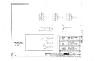
This document is a schematic diagram for a circuit titled "THREE 2-2-2-3 AND-OR GATES M181," created by Digital Equipment Corporation and copyrighted in 1970.
Key aspects of the document include:
- Purpose: The schematic is for "TEST AND MAINTENANCE PURPOSES" only, and the circuits are proprietary.
- Circuit Description: It depicts three AND-OR gate modules (E1, E2, E3) with various inputs and outputs (e.g., CI, K2, S2). The circuit includes connections for +5V, +3V, and ground (GND), along with several capacitors (C1-C6) and resistors (R1, R2) for power filtering and circuit operation.
Component Specifications (General Notes):
- Unless otherwise indicated, capacitors are 0.1uF, 100V, 20%.
- Integrated Circuits (ICs) are specified as DEC1074H52, with Pin 7 connected to GND and Pin 14 to +5V on all ICs.
Parts List: A detailed list provides item numbers, DEC part numbers, descriptions, and quantities for components such as:
- DEC1074H52 ICs.
- Resistors (220 Ohm and 330 Ohm, 1/4W, 5% CC).
- Capacitors (0.01uF, 100V, 20% DISC and 39uF, 10V, 10% TANT).
- Mechanical parts like "HANDLE, FLIP CHIP - MAGENTA" and "EYELET #GS 4-7."
- The "ETCHED CIRCUIT BOARD" itself, along with related documentation.
Metadata: The drawing was prepared by Nancy Moore on December 8, 1970, and has the number M181-0-1.
Site structure and layout ©2025 Majenko Technologies