M175
Order Number: XX-14BE6-B3
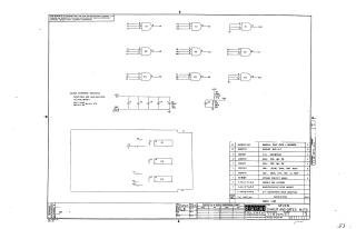
This document is a proprietary schematic diagram from Digital Equipment Corporation, copyrighted 1970, for a circuit titled "SEVEN 3 INPUT AND GATES M175" (Document Number M175-0-1, Revision A). It is explicitly furnished for test and maintenance purposes.
The schematic illustrates a circuit primarily composed of multiple 3-input AND gates (labeled E1, E2, E3). General notes indicate that the integrated circuits (ICs) used are DECIØ74HI1, with standard power connections: Pin 7 to Ground (GND) and Pin 14 to +5V.
The design includes power supply filtering with various capacitors (e.g., .01uF, 39uF) and resistors (e.g., 220 Ohm, 330 Ohm). A comprehensive parts list details all components, ranging from the ICs, capacitors, and resistors to mechanical items like a "HANDLE, FLIP CHIP" and "EYELET." The document also references associated manufacturing and assembly information such as a "MODULE ECO HISTORY" and "ASSY/DRILLING HOLE LAYOUT."
Site structure and layout ©2025 Majenko Technologies