M170
Order Number: XX-CF859-8F
This document is a proprietary schematic diagram, copyrighted by Digital Equipment Corporation in 1970, provided for test and maintenance purposes.
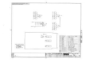
The schematic depicts an "8 WIDE AND-NOR M170" circuit, featuring several digital logic gates. Key components include multiple 8-input NAND gates (labeled E2 and E3, implemented with DEC1074H53 Integrated Circuits) and other logic gates (labeled E1, implemented with a DEC1074H62 Integrated Circuit). Power connections for +5V and Ground are indicated, along with associated filtering components such as capacitors (e.g., 39µF, .01µF) and resistors (e.g., 220 Ohm, 330 Ohm). General notes specify that all ICs use Pin 7 for Ground and Pin 14 for +5V, and default capacitor values are 0.01uF, 100V, 20%.
A detailed parts list enumerates all components required, including specific ICs, various resistors and capacitors, an etched circuit board, eyelets, and a "FLIP CHIP" handle. The document itself is identified as Number M170-0-1, Revision B, with Printed Circuit Revision 8.
Site structure and layout ©2025 Majenko Technologies