M162
Order Number: XX-B5305-78
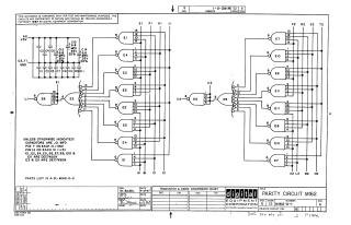
This document is a circuit schematic for a Parity Circuit MI62, designed and copyrighted by Digital Equipment Corporation in 1967.
Key information includes:
- Purpose: The schematic is for test and maintenance purposes, featuring proprietary circuits.
- Components: It primarily consists of integrated circuits (ICs) labeled E1 through E11. Most are DEC7420N, while E3 and E9 are DEC7430N. Various capacitors are also present, including .01 MFD for C1-C11 and +6.8 MFD, 35V, 20% for C12-C14.
- Power & Ground: The circuit operates with a +5V supply (A2) and Ground (C2, T1). Standard IC power connections specify Pin 7 as Ground and Pin 14 as +5V.
- Associated Documentation: A parts list, A-PL-M162-0-0, is referenced.
- Revision/Production Details: The circuit is a printed circuit (Rev. B) and was drawn on 4-18-67 by M. Haller and checked on 5/5/67.
Site structure and layout ©2025 Majenko Technologies