M141
Order Number: XX-7882D-F3
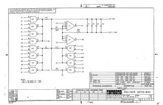
This document is a proprietary schematic diagram for the AND/NOR GATES M141 circuit, copyrighted by Digital Equipment Corporation in 1967. It is intended solely for test and maintenance purposes.
The schematic details a digital logic circuit featuring:
- Integrated Circuits (ICs): Specifically, DEC7420N (designated E1) and DEC7401N (designated E2, E3, E4), which perform AND/NOR logic functions.
- Passive Components: Various resistors (R1-R6) with specified values (330 Ohm, 750 Ohm, 1.5K Ohm) and capacitors (C1-C4) of 0.01 MFD.
- Power Supply: The ICs are powered by +5V (Pin 14) and connected to ground (Pin 7).
A detailed parts list provides the reference designations, descriptions, and Digital Equipment Corporation part numbers for all components used in the circuit. The document includes revision history and was drawn and checked in October 1967.
Site structure and layout ©2025 Majenko Technologies