M002
Order Number: XX-E452E-F8
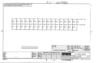
This document is a proprietary circuit schematic from Digital Equipment Corporation, copyrighted 1968, intended solely for test and maintenance purposes.
Titled "15 LOADS M002" (drawing number M002-0-1, Revision A), it depicts a circuit primarily composed of fifteen resistive load sections. These sections feature pairs of resistors (R16-R30 and R1-R15) connected in parallel between a +5V power rail (labeled 'A') and ground (labeled 'C'), creating multiple intermediate test or load points (labeled V, U, T, S, R, P, N, M, L, K, J, H, F, E, D). A capacitor (C1) is also included, connected between the +5V and ground rails.
The accompanying Parts List details the components:
- Resistors R16-R30: 1.8 KΩ, 1/4W, 10% tolerance (Part No. 1301428).
- Resistors R1-R15: 3.3 KΩ, 1/4W, 5% tolerance (Part No. 1300439).
- Capacitor C1: 0.01 µF, 100V, 20% tolerance (Part No. 1001610).
The document was drawn, checked, and engineered between June and July 1968.
Site structure and layout ©2025 Majenko Technologies