G828
Order Number: XX-11D78-78
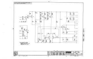
This document is an electronic schematic titled "6V REGULATOR CONTROL G828" (Document Number G828-0-1, Revision A), created by Digital Equipment Corporation and copyrighted in 1970.
Key information presented:
- Purpose: It details the circuitry for a 6V regulator control system, explicitly stating it's for test and maintenance purposes and is proprietary.
- Components: The schematic illustrates a complex circuit using numerous transistors (Q1-Q10), diodes (D1-D13, including Zener diodes), resistors (R1-R35), and capacitors (C1-C8), along with various labeled connection points (e.g., AP, AS, BF, BE).
- Component Specifications: Default specifications are provided for components: resistors are 1/4W, 10%; capacitors are .01MFD, 100V, 20%; diodes are D664; and transistors are DEC6534D, unless otherwise indicated.
- Conversion Chart: A "TRANSISTOR & DIODE CONVERSION CHART" cross-references Digital Equipment Corporation (DEC) part numbers with their Electronic Industries Alliance (EIA) equivalents for various semiconductors used in the circuit.
- Authorship & Dates: It includes drawing, checking, engineering, and production approval dates and names, primarily from early 1970.
Site structure and layout ©2025 Majenko Technologies