G810
Order Number: XX-7F6B4-2C
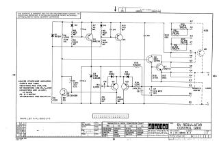
This document is a circuit schematic for a "6V REGULATOR CONTROL G810," published in 1967 by Digital Equipment Corporation. It is intended for test and maintenance purposes and is noted as proprietary.
The schematic details an electronic circuit featuring multiple transistors (e.g., Q1-Q7), diodes (e.g., D1-D6), resistors, and capacitors arranged to perform voltage regulation. It includes an adjustable potentiometer (R9 labeled 'CW'), and an output section labeled 'LOAD' with various connection points (AP to BV) and a 'REMOTE SENSE' capability.
Accompanying the diagram are general specifications for components (e.g., default resistor tolerances, capacitor values, diode types, and transistor models), a "TRANSISTOR & DIODE CONVERSION CHART" listing DEC part numbers and their EIA equivalents, and a revision history. A "PARTS LIST A-PL-6810-0-0" is also referenced.
Site structure and layout ©2025 Majenko Technologies