G7005
Order Number: XX-4C171-D2
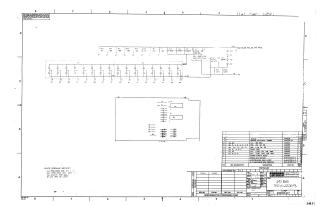
This document is an electrical schematic titled "I/O BUS TERMINATOR #3," created by Digital Equipment Corporation.
The schematic details the circuit design for an I/O bus termination module, primarily featuring:
- Components: A network of resistors (R1-R13, including 100Ω and 1.5kΩ values), capacitors (C1-C6, including 3.9µF and 0.01µF values), diodes (D1-D5, identified as D662 type), and two Integrated Circuits (E1, E2, identified as DEC 2501).
- Power Rails: Connections to various voltage levels, including -0.7V, -2.8V, -5V, and +14V.
- Connections: Numerous labeled connection points (e.g., A1, B1, P5, L1, S1, T2) that likely interface with the I/O bus.
Accompanying the schematic are:
- General Specifications: Notes indicating default tolerances for components (all resistors are 5%, all capacitors are 20%).
- Parts List: A comprehensive table detailing the quantity, reference designation, description, and part number for all components, including the etched circuit board, ICs, resistors, capacitors, diodes, and even a "HANDLE, FLIP CHIP - GREEN."
- Proprietary Notice: A statement asserting that the drawing and specifications are the property of Digital Equipment Corporation and cannot be reproduced or used without written permission.
The document is identified by Drawing Number G7005-0-1, Revision A.
Site structure and layout ©2025 Majenko Technologies