G700
Order Number: XX-1ED82-6A
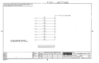
This document is a schematic diagram for a 100Ω Terminator G700, produced by Digital Equipment Corporation, copyrighted in 1966.
Key features of the schematic include:
- Circuit Function: It depicts a resistor network designed as a terminator.
- Components: Nine individual resistors (R1 through R9) are shown.
- Resistor Specifications: Unless otherwise indicated, all resistors are 100 Ohms, 1/4 Watt, with a 5% tolerance.
- Connections: Each of nine input lines (D, E, H, K, M, P, S, T, V) is connected through its respective resistor (R1-R9) to a common output node. This common node is also designated as Ground (GND) and serves as additional connection points (C, F, J, L, N, R, U).
- Purpose & Proprietary Information: The schematic is provided solely for test and maintenance purposes, and the circuits are proprietary in nature.
- Administrative Details:
- Part Number: G700-0-1
- Revision: A
- Company: Digital Equipment Corporation, Maynard, Massachusetts
- Dates: Drawn on 11-10-66 by M. Haller, checked by R. Schubert and J.E. Krew on 11-14-66.
Site structure and layout ©2025 Majenko Technologies