G062
Order Number: XX-F76B1-66
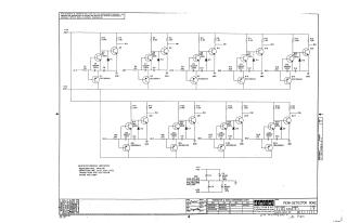
This document is a schematic diagram for a Peak Detector, model G062, developed by Digital Equipment Corporation (DEC) and copyrighted in 1970.
Key information:
- Purpose & Confidentiality: The schematic is proprietary, intended solely for test and maintenance purposes.
- Circuit Design: The main circuit features multiple repeating stages, each primarily comprising two transistors (DEC 6531 and DEC 6534B), a diode, various resistors, and capacitors. These stages likely represent individual peak detector channels or cascaded detection elements.
- Power Supply: The circuit operates using +5V and -15V power rails, with large decoupling capacitors (100µF, 20V) shown for these supplies.
Component Specifications (General & Specific):
- Resistors: Generally 1/4W, 5% tolerance.
- Capacitors: Generally 0.01µF, 100V, 20% (note), though many on the schematic are specifically 1000pF, 250V.
- Transistors: Identified as DEC 6531 and DEC 6534B, with a conversion chart providing EIA equivalents (MPS6531, MPS6534). A general note also lists DEC 30098 (EIA 2N30098).
- Diodes: Identified as D664, with a conversion chart providing the EIA equivalent (IN3606).
Revisions: The document is at Revision D.
Site structure and layout ©2025 Majenko Technologies