G021
Order Number: XX-D7FE1-5B
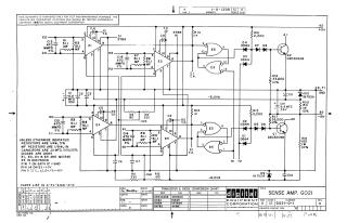
This document is a proprietary electronic schematic diagram, copyrighted 1967 by Digital Equipment Corporation, for a device titled "SENSE AMP. G021" (part number G021-0-1, revision K). It is intended for test and maintenance purposes.
The circuit primarily utilizes:
- MC1540 integrated circuits (E1, E2, E4, E5), which are differential/sense amplifiers, suggesting multiple stages of signal amplification.
- DEC7400N integrated circuits (E3), which are NAND gates, indicating digital logic processing.
- Transistors: DEC3009B (equivalent to 2N3009).
- Diodes: D662 (IN645), D664 (IN3606), and IN753.
- Various resistors and capacitors.
The schematic specifies standard component characteristics:
- Resistors: 1/4W, 5% (general) or 1/8W, 1% (MF resistors).
- Capacitors: .01 MFD, 100V, 20% (general).
- Integrated Circuit Power: Pin 7 of all ICs is connected to Ground (GND), Pin 14 of E3 to +5V, and Pin 2 of E1, E2, E4, E5 to +5V.
The circuit operates with several power rails, including +5V, -15V, -6.2VA, -6.2VB, -4VA, and GND, and includes multiple labeled test points (T.P.). A separate "PARTS LIST IS A-PL-G021-0-0" is referenced.
Site structure and layout ©2025 Majenko Technologies