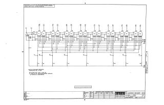
FM ADDRESS DECODER B199
Order Number: B199-0-1
This document is a schematic diagram for an FM Address Decoder, identified as B199. The circuit primarily features eight dual 4-input NAND gates (E1 through E8), specified as Texas Instruments SN7440N or Fairchild U6A900959X components, interconnected with numerous capacitors (C1-C19) and resistors (R1-R8). Power supply connections include +1.8V, -3V, and -15V, alongside various input/output signal lines. General component specifications state that capacitors are .01 MFD unless otherwise indicated, and resistors are 1,500 ohms, 1/4 watt, 5%. A note indicates the schematic is proprietary, for test and maintenance purposes, and copyrighted by Digital Equipment Corporation in 1967.
Site structure and layout ©2025 Majenko Technologies