PROTECTION COMPARATOR B198
Order Number: B198-0-1
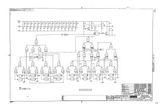
This document is a detailed schematic diagram for a "Protection Comparator B198," copyrighted by Digital Equipment Corporation in 1966. It illustrates the circuitry for a module designed for test and maintenance purposes, featuring both analog and digital components.
The schematic includes:
- Power Supply and Filtering: A comprehensive arrangement of capacitors (C1-C36) connected to multiple voltage rails, including ground, +1.8V, -3V, +10V, and -15V, for stabilization and filtering.
- Analog Sensing/Comparison: A section featuring transistors (Q1, Q2) and resistors (R1-R8) that likely condition signals or perform initial voltage comparisons, providing inputs to the digital logic. A note defines "LOW = MA > PR" and "HI = MA <= PR," indicating a comparison function.
- Digital Logic Network: A complex interconnection of various integrated circuits (E1-E14) configured as logic gates. This network processes signals, potentially comparing "MA" (Memory Address or similar) signals against "PR" (Protection Register or similar) values to generate protection-related outputs. Several test points (T.P.1 through T.P.6) are included for diagnostic purposes.
- Component Details: A "PARTS LIST" provides a breakdown of all integrated circuits, transistors, resistors, and capacitors used in the design, including their specific DEC part numbers.
- Operating Notes: Key voltage requirements for the integrated circuits are specified (PIN 7 at -3V, PIN 14 at +1.8V).
Site structure and layout ©2025 Majenko Technologies