DIODE GATE B173
Order Number: B173-0-1
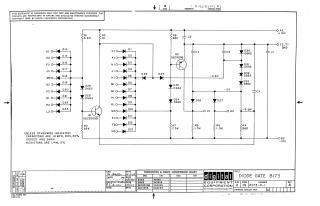
This document is a schematic diagram for a "DIODE GATE B173" circuit, copyrighted in 1969 by Digital Equipment Corporation. It is provided for test and maintenance purposes, emphasizing its proprietary nature. The schematic details various diode inputs (D1-D23) leading into a complex arrangement of diodes (D24-D35), resistors (R1-R8), capacitors (C1-C5), and two transistors (Q1: DEC3009B/2N3009, Q2: DEC4258/2N4258). The circuit operates with multiple voltage levels including +10V, GND, -0.6V, -3V, -3.0V, and -15V. A conversion chart is included for transistors and diodes, mapping DEC part numbers to their EIA equivalents. General specifications state that capacitors are .01 MFD, 100V, 20%; diodes are D664 (IN3606); and resistors are 1/4W, 5%, unless otherwise indicated.
Site structure and layout ©2025 Majenko Technologies