DIODE GATE B172
Order Number: B172-0-1
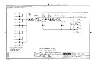
This document is a proprietary schematic diagram copyrighted by Digital Equipment Corporation in 1967, intended for test and maintenance purposes. It details the circuit for a "Diode Gate B172." The circuit features multiple diode inputs (HO-VO) feeding into two transistor stages (Q1 and Q2, type 2N4258B) via various resistors and diodes. Key components include numerous diodes (D1-D23, types D-662, D-664), resistors (R1-R7, with specified values and 5% tolerance), and a capacitor (C1, .01 MFD). The schematic indicates connections to power supplies such as +10V, -15V, ground, and -3V, and defines outputs OD, OE, and OF. A conversion chart for transistors and diodes (2N4258B, D662, D664) to EIA equivalents is included. General notes specify that resistors are 1/4W, 10%, and capacitors are MMFD, with diodes generally being D-664 unless otherwise specified. It also directs to use the etch board of the B171.
Site structure and layout ©2025 Majenko Technologies