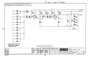
DIODE GATE B171
Order Number: B171-0-1
This document presents a schematic diagram for a "DIODE GATE B171" circuit, copyrighted by Digital Equipment Corporation in 1964. The circuit design is proprietary and intended for test and maintenance purposes.
The schematic illustrates a complex electronic circuit utilizing multiple diode inputs (D1-D12) which feed into a common signal path. This path then branches through diode-resistor networks (R1-R6, D13, D14, D16, D17, D23) to drive the bases of two transistors, Q1 and Q2 (DEC 2894-1). Additional diodes (D15, D18) are part of the transistor output stages. The circuit is powered by +10V, -15V, and ground connections, and includes a -3V "STRATE" line with a diode string (D19-D22) and a capacitor (C1).
General component specifications are listed: resistors are 1/4W, 10% (unless otherwise noted), capacitors are MMFD, and diodes are D-664 (unless otherwise noted). A conversion chart provides equivalent EIA part numbers for the DEC transistors (DEC2894-1) and diodes (D662, D664) used in the design. The schematic was drawn by A. Ouellette and checked by N. Perryman in June 1964.
Site structure and layout ©2025 Majenko Technologies