DIODE GATE B141
Order Number: B141-0-1
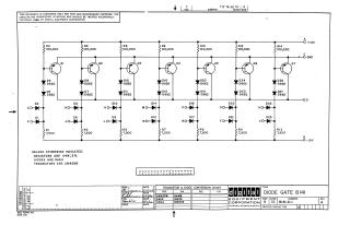
This document is a proprietary schematic diagram for a "DIODE GATE B141" circuit, copyrighted in 1966 by Digital Equipment Corporation, intended solely for test and maintenance. The circuit features a network of seven transistors (Q1-Q7), numerous diodes (primarily D662 and D664 types), and resistors. Power inputs include +10V, Ground (GND), and -15V, with an output labeled OD and various signal inputs (E0, F0, H0, J0, K0, L0, M0, N0, P0, R0, S0, T0, U0, V0). General specifications indicate resistors are 1/4W, 5%, diodes are D664, and transistors are 2N4258, unless otherwise noted. A conversion chart provides EIA equivalents for the specified DEC components: 2N4258 for transistors, IN645 for D662 diodes, and IN3606 for D664 diodes. The document is at Revision A.
Site structure and layout ©2025 Majenko Technologies