Adder B138
Order Number: B-CS-B138-0-1
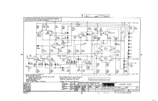
This document is a proprietary circuit schematic for an "ADDER B138" module, created by Digital Equipment Corporation and copyrighted in 1967. It is intended solely for test and maintenance purposes.
The schematic provides a detailed diagram of the adder circuit, featuring numerous transistors (e.g., DEC3009B, DEC3639B, SDA-8), diodes (e.g., D662, D668, FD777), resistors, and capacitors. It specifies general characteristics for components, such as resistor wattage and tolerance (1/4W 5%, metal film 1/8W 1%), capacitor values (0.01 MFD), and specific diode types (D662, D668).
Key sections include a "Transistor & Diode Conversion Chart" which cross-references DEC part numbers with EIA equivalents, and notes regarding various power supply voltages (+6V, +5.25V, -2.1V, +1.5V, -0.6V, +10V, -15V). The document references an external parts list (A-PL-B138-0-0) and contains a revision history, identifying itself as B138-0-1, Printed Circuit Rev. B. It also mentions connections for carry signals between modules.
Site structure and layout ©2025 Majenko Technologies