Diode Gate B137
Order Number: B-CS-B137-0-1
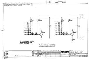
This document is an electronic schematic diagram for a Diode Gate BI37, designated as B137-0-1, Revision B, created by Digital Equipment Corporation and copyrighted in 1966.
The schematic is intended for test and maintenance purposes and describes a proprietary circuit. It features two primary gate sections, each utilizing a bank of input diodes (D1-D6, D9-D14 respectively) feeding into a transistor (Q1 and Q2, both 2N4258 types). The circuit incorporates resistors (R1-R4, with default 1/4W, 10% specifications), additional diodes (D7, D8, D15, D16, predominantly D-662 and D-664 types), and capacitors (C1, C2). It operates with power rails of +10V, -15V, and ground connections.
Key information includes a transistor and diode conversion chart (DEC to EIA part numbers) and a note indicating the use of the B117 etch board.
Site structure and layout ©2025 Majenko Technologies