Diode Gate B136
Order Number: B-CS-B136-0-1
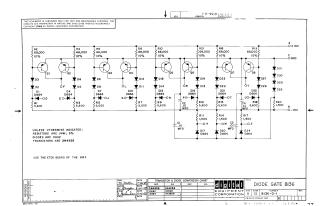
This document is a schematic diagram titled "DIODE GATE BI36" from Digital Equipment Corporation, copyrighted in 1969.
Key information:
- Purpose: The schematic is for test and maintenance purposes, featuring proprietary circuits.
- Circuit Type: It details a "Diode Gate" circuit, likely a logic gate or a similar switching circuit, utilizing multiple transistors (Q1-Q8) and numerous diodes and resistors.
Components:
- Resistors: Primarily 1/4W, 5% tolerance, with some high-value resistors (e.g., 68,000 ohms) explicitly noted with 10% tolerance. Other common values are 5,600 ohms and 1,500 ohms.
- Diodes: The main type is D662 (EIA equivalent: 1N645), with D664 (EIA equivalent: 1N3606) also used.
- Transistors: All specified as 2N4258.
- Capacitors: Several 0.01 MFD capacitors are included.
Power Supplies: The circuit operates with a +10V supply (point A), -15V supply (point B), and Ground (point C).
- Fabrication Note: It instructs to "USE THE ETCH BOARD OF THE B134".
Site structure and layout ©2025 Majenko Technologies