3 Bit Parity Circuit B130
Order Number: B-CS-B130-0-1
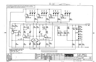
This document is a schematic diagram for a "3 BIT PARITY CIRCUIT B130", developed by Digital Equipment Corporation (DEC) in 1964.
Key information includes:
- Purpose: Furnished for test and maintenance purposes, emphasizing its proprietary nature.
- Circuit Function: Designed to generate or check 3-bit parity, utilizing a combination of transistors (e.g., DEC2894-1B, DEC3009A), diodes (e.g., D-662, D664), resistors, capacitors, inductors, and an SDA-8 integrated circuit (Q4).
- Inputs/Outputs: Features various input points (labeled V through J), output signals ("OUT 'O'" and "OUT 'I'"), and power supply connections (+10V, -15V, -2.2V, -4.5V, GND).
- Component Specifications: Resistors are generally 1/4W, 5% tolerance, and diodes are D664 unless otherwise indicated.
- Supporting Information: Includes a "Transistor & Diode Conversion Chart" mapping DEC part numbers to EIA equivalents (e.g., DEC3009A to 2N3009, D662 to 1N645, D664 to 1N36C6), a reference to a "Parts List A-PL-B130-0-0", and a revision history table.
- Authorship: Drawn by H.W. Porter, checked by N. Perryman, and engineered by R. Doane in late 1964.
Site structure and layout ©2025 Majenko Technologies