Diode Gate B113
Order Number: B-CS-B113-0-1
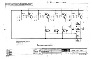
This document is a schematic diagram for an electronic circuit titled "DIODE GATE BII3", copyrighted in 1964 by Digital Equipment Corporation.
Key Information:
- Purpose: The schematic is for test and maintenance purposes only and is proprietary to Digital Equipment Corporation.
- Circuit Description: It depicts a multi-stage diode-transistor logic (DTL) gate circuit. Each stage features input diodes, series resistors, and a transistor (Q1, Q2, Q3).
- Components: The circuit includes numerous resistors (R1-R12, with values such as 12,000, 68,000, 1,500 ohms), diodes (D1-D23, primarily D-662), transistors (Q1, Q2, Q3), and capacitors (C1, C2, C3, all .01 MFD).
- Power/Ground: It indicates a "-3V" power rail and "OC GND" (ground).
General Specifications:
- Resistors: 1/4W, 5% (unless otherwise indicated).
- Transistors: DEC2894-1B.
- Diodes: D-664 (unless otherwise indicated, though many are specified as D-662).
Conversion Chart: A "Transistor & Diode Conversion Chart" provides DEC part numbers and their EIA equivalents (e.g., D662 = IN645, D664 = IN3606).
- Dates: The drawing, checking, and engineering dates are in late April and early May 1964.
- Revisions: The document is at Revision D for the schematic and Revision C for the printed circuit.
Site structure and layout ©2025 Majenko Technologies