Diode Gate B105
Order Number: B-CS-B105-0-1
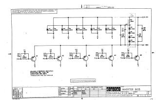
This document is a proprietary schematic diagram for an "INVERTER BIO5" circuit, created and copyrighted in 1964 by Digital Equipment Corporation (DEC). It is intended solely for test and maintenance purposes.
The circuit features:
- An upper section with multiple diode-resistor pairs (D1-D5 with R3, R4, R6, R7, R9) acting as inputs, connected to a -3V reference system which includes diodes (D6-D9), a resistor (R11), and capacitors (C5, C6, C8, C9). This section is powered by -15V and ground.
- A lower section comprising five transistor-based inverter stages (Q1-Q5), each with an input network of a resistor (R1, R2, R5, R8, R10) and a parallel capacitor (C1-C4, C7).
Component Specifications:
- Resistors are generally 1/4W, 5%.
- Capacitors are specified in MMFD (picofarads).
- Transistors are DEC 2894-IB.
- A conversion chart notes DEC diodes D662 as EIA IN645 and D664 as EIA IN3606.
The document is Revision E (with Printed Circuit Revision D) and was drawn in April 1964 by H. Porter, checked by N. Perryman, and engineered by B. Scrudney.
Site structure and layout ©2025 Majenko Technologies