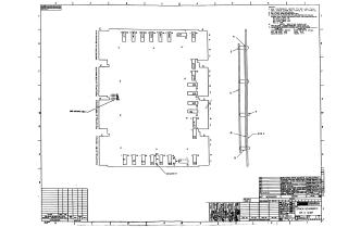
Stack Schematic 8K X 12 Bit
Order Number: XX-XXXXX-XX
This document provides a set of technical schematics and component specifications for an 8K x 12-bit memory stack assembly.
Key Content Includes:
- Assembly and Schematic Diagrams: Detailed diagrams illustrating the layout, jumper configurations, and circuit paths for the memory stack module.
- Component Lists: Tables detailing the required components, including part numbers, descriptions, and manufacturer specifications (e.g., transistors, resistors, diodes, and ICs).
- Technical Notes: Specific instructions regarding component lead lengths, assembly procedures for split lugs and grommets, and guidelines for interchangeable components.
- Memory Configurations: Information regarding allowable memory system configurations, specifying the required stack types (H212 or H212A) and their compatibility with specific current sources and driver boards (G11, G11S, G233, or G234).
- Modification/Repair Data: Information on component substitution and jumper connections, as well as instructions for magnet wire termination and solder points on the printed circuit board.
Site structure and layout ©2025 Majenko Technologies