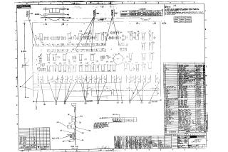
Front Panel Control Board
Order Number: XX-XXXXX-XX
This document provides the technical schematics and parts lists for the "Front Panel Control Board" manufactured by Digital Equipment Corporation.
The document consists of two primary types of technical drawings:
- Physical Assembly/Layout: Includes mechanical drawings showing the physical layout of components, jumpers, and switches on the board, along with a parts list detailing specific hardware, resistors, capacitors, and LED indicators.
- Logic Schematics: Detailed electrical circuit diagrams illustrating the logic gates, flip-flops, and interconnections. These diagrams map out the control signals (such as "Mem Start," "Single Step," "Halt," and "Load Address") and the data path indicators (D8 through D34) used for monitoring and controlling the computer system.
The notes specify component requirements, such as the use of specific light-emitting diodes (LEDs) and momentary switches, and provide a reference index for the integrated circuits (ICs) utilized throughout the board's logic design.
Site structure and layout ©2025 Majenko Technologies