Engineering Drawings
Order Number: XX-XXXXX-XX
This document, Chapter 10 of a manual, provides comprehensive technical information regarding engineering drawings for DEC equipment, specifically for the PDP-8 computer.
Key contents include:
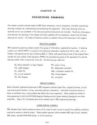
- Drawing Numbering System: An explanation of how DEC engineering drawing numbers are structured using a five-part, hyphen-separated code to indicate drawing type, size, equipment number, and serial series.
- Symbol Standards: Definitions of circuit and logic signal symbols used in the schematics, including specific pulse and logic level definitions (ground vs. -3V levels).
- Engineering Schematics: A large collection of detailed block and circuit schematics for various components, including power supplies, memory selectors, diode gates, and register control circuits.
- Standardization: Tables for semiconductor substitution to assist in maintenance and repair using standard EIA components.
- S-Series Modules: Technical details on S-series module adaptations for the PDP-8.
- Connector Wiring: Tables listing pin assignments and color-coding for indicator and chassis connectors.
- Appendices: A "Signal Origins" table (Appendix 1) to help trace specific signals to their relevant engineering drawings, and a list of available software from the Digital Program Library (Appendix 2).
Site structure and layout ©2025 Majenko Technologies