Power Supply 728
Order Number: Z728
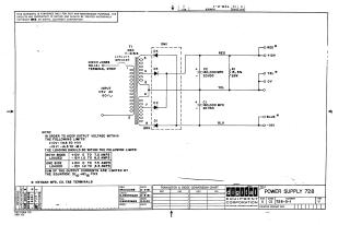
This document is a technical schematic for a Digital Equipment Corporation power supply, dated 1963. It outlines the circuitry for a transformer-based power supply unit designed to provide regulated output voltages of +10V and -15V from a 115V AC input.
Key details provided in the schematic include:
- Circuit Components: The design utilizes a transformer (DEC T-41513), a diode bridge configuration (D1–D4), and two large capacitors (160,000 MFD, 20VDC) for filtering.
- Operating Limits: The document specifies that output voltages must be maintained within +9.5V to +11V for the +10V rail and -14.5V to -16V for the -15V rail.
- Load Specifications: It provides specific current load limits for when both sides are loaded versus when only one side is loaded. It also includes an equation ($5I{10} + 6I{15} \le 53$) to calculate the total allowable sum of output currents.
Site structure and layout ©2025 Majenko Technologies