Power Sequence and Crobar
Order Number: W519
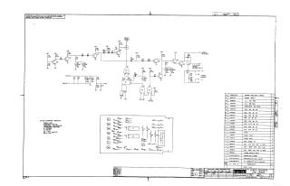
This document is a technical schematic and parts list for a "Power Sequence and Crobar" circuit board designed by the Digital Equipment Corporation.
The schematic details the circuitry responsible for managing power sequencing and the "crobar" protection mechanism, which is designed to protect equipment by triggering a release if certain voltage or operational parameters are exceeded. The document includes:
- Circuit Diagram: A detailed layout of transistors, diodes, capacitors, and resistors (including integrated circuits DEC 9601 and DEC 7401) that comprise the power control logic.
- Parts List: A comprehensive table identifying the specific electrical components, including resistors of various values, capacitors (electrolytic and tantalum), diodes (D664), a relay, and the etched circuit card itself.
- Specifications: Notes on standard operating values (resistors at 1/4W, 5%; capacitors at 0.1uF, 100V, 20%) and pin configurations for the integrated circuits.
Site structure and layout ©2025 Majenko Technologies