Clamp Loads W002
Order Number: W002
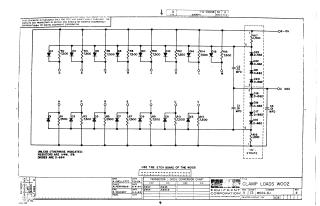
This document is a technical schematic for a "Clamp Loads W002" circuit board produced by the Digital Equipment Corporation in 1964. The circuit is designed to provide clamping functionality using an array of diodes (D1–D16 and D2–D15) and 7,500-ohm resistors, connected to -15V and -3V power rails. It also includes a secondary column of diodes (D16–D23) for voltage regulation and filtering using capacitors C1, C2, and C3. The schematic includes component specifications (1/4W, 5% resistors; D-664 diodes) and notes that the board uses the etch layout of the W005 board.
Site structure and layout ©2025 Majenko Technologies