Inverter S107
Order Number: S107
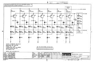
Summary: This document is a technical schematic diagram for the Digital Equipment Corporation (DEC) Inverter S107, dated June 1965. The circuit consists of an array of seven transistors (Q1 through Q7) paired with various diodes (D1-D7, D12-D24, D32) and resistors (R1-R7, R8-R22). It includes a transistor and diode conversion chart and specifies that the board should use the etch pattern for the R107 model. The schematic is intended for test and maintenance purposes and serves as a reference for the component configuration of the S107 inverter module.
Site structure and layout ©2025 Majenko Technologies