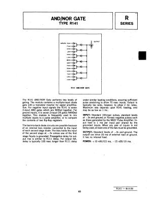
Diode Gate R141
Order Number: R141
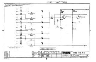
This document is a technical schematic for a Digital Equipment Corporation "Diode Gate" circuit (model R141), dated July 1964. The circuit utilizes an array of diodes (D1–D14) connected to inputs E through V, which feed into a secondary stage of diodes (D15–D22) and an amplifier section comprised of two transistors (Q1 DEC3009B and Q2 DEC3639B). The schematic includes standard voltage rails of +10V and -15V, along with various resistor and capacitor specifications. A conversion chart at the bottom identifies the specific component equivalents for the diodes and transistors used in the design.
Site structure and layout ©2025 Majenko Technologies