Jumper/Extender Board M941
Order Number: M941
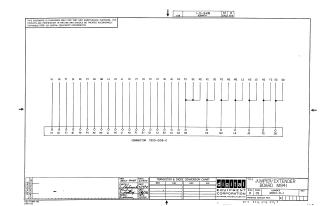
Summary: This document is a technical schematic diagram for the Digital Equipment Corporation M941 Jumper/Extender board, dated April 1970. The schematic illustrates the pin-to-pin wiring configuration for a connector assembly (7900-0155-0), showing how specific pins (such as C2, S2, R2, V2, P2, N2, M2, L2, K2, J2, F2, and E2) are jumpered or routed across the board. It includes standard drafting information, such as revision status, approval signatures, and a reference for a transistor and diode conversion chart.
Site structure and layout ©2025 Majenko Technologies