Unibus Drivers M783
Order Number: M783
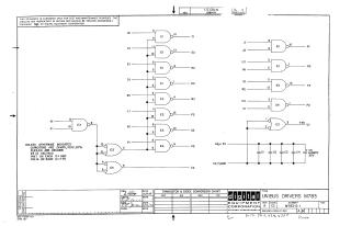
Summary: This document is a technical schematic for the "Unibus Drivers M783," manufactured by Digital Equipment Corporation (dated 1969). The circuit diagram illustrates a series of logic gates used for signal buffering and conversion.
Key details include:
- Components: The board utilizes DEC881 logic gates and DEC7400 integrated circuits.
- Functionality: It maps various input signals (BI, AI, EI, DI, MI, LI, RI, PI, JI, J2, L2, NI, SI, R2, V2, VI) to corresponding output signals (CI, E2, H2, K2, M2, P2, S2, U2, KI, N2, T2, F2).
- Power Requirements: The schematic specifies a +3V output (UI), as well as connections for +5V and Ground, supported by a bank of decoupling capacitors (including one 6.8MFD 35V electrolytic capacitor).
- Specifications: All unspecified capacitors are .01MFD, 100V, 20%. Pin 7 of each IC is connected to ground, and Pin 14 is connected to +5V.
Site structure and layout ©2025 Majenko Technologies